


DC-DC Converters
(Industrial - SMD)
DC-DC Converters
(Industrial - THT)
DC-DC Converters
(Railway)
DC-DC Converters
(Telecom Power)
DC-DC Converters
(Photovoltaic)
DC-DC Converters
(IGBT & SiC)


Series |
Case Size |
Input Range |
Input Voltage (VDC) |
Output Voltage (VDC) |
Output Current (A) |
Isolation (kVDC) |
Regulation |
SCP * |
η max. |
Operating Temp. |
Dimming |
Certs |
||||||||||||||||||||||||||||||||||||||||||||||||||||||||||||||||||||||||||||||||||||||||||||||||||||||||||||||||||||||||||||||||||||||||||||||||||||||||||||||||||||||||||||||||||||||||||||||||||||||||||||||||||||||||||||||||||||||||||||||||||||||||||||||||||||||||||||||||||||||||||||||||||||||||
 | QS7A_3UP | SIP7 | ±10% | 3.3; 5; 12; 15 | 3.3; 5; 9; 12; 15; 24 | QS7A_3UP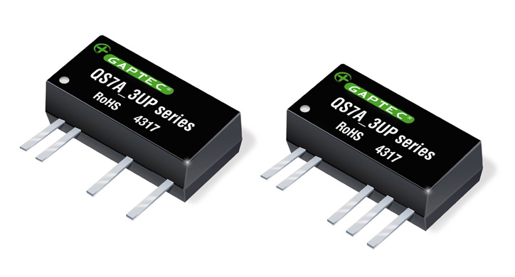
Download PCB Footprints and Schematic Symbols for free, to download/request, please click the Logo on the right in the below Selection Guide.   
| ||||||||||||||||||||||||||||||||||||||||||||||||||||||||||||||||||||||||||||||||||||||||||||||||||||||||||||||||||||||||||||||||||||||||||||||||||||||||||||||||||||||||||||||||||||||||||||||||||||||||||||||||||||||||||||||||||||||||||||||||||||||||||||||||||||||||||||||||||||||||||||||||||||||||||||||
| QS4E_1U | SIP4 | ±10% | 3.3; 5; 7,2; 12; 15; 24; 48 | 3.3; 5; 7.2; 9; 12; 15; 24 | 1 | 74% | -40°C - +85°C | QS4E_1U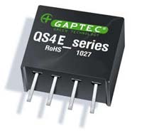
The QS4E_1U series is specially designed for applications where a group of polar power supplies are isolated from the input power supply in a distributed power supply system on a circuit board. Features:
Download PCB Footprints and Schematic Symbols for free, to download/request, please click the Logo on the right in the below Selection Guide.
| |||||||||||||||||||||||||||||||||||||||||||||||||||||||||||||||||||||||||||||||||||||||||||||||||||||||||||||||||||||||||||||||||||||||||||||||||||||||||||||||||||||||||||||||||||||||||||||||||||||||||||||||||||||||||||||||||||||||||||||||||||||||||||||||||||||||||||||||||||||||||||||||||||||||||||
| QS4E_3U | SIP4 | ±10% | 3.3; 5; 7,2; 12; 15; 24; 48 | 3.3; 5; 7.2; 9; 12; 15; 24 | 3 | 76% | -40°C - +85°C | QS4E_3U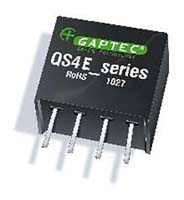
The QS4E_3U series is specially designed for applications where a group of polar power supplies are isolated from the input power supply in a distributed power supply system on a circuit board. Features:
Download PCB Footprints and Schematic Symbols for free, to download/request, please click the Logo on the right in the below Selection Guide.
| |||||||||||||||||||||||||||||||||||||||||||||||||||||||||||||||||||||||||||||||||||||||||||||||||||||||||||||||||||||||||||||||||||||||||||||||||||||||||||||||||||||||||||||||||||||||||||||||||||||||||||||||||||||||||||||||||||||||||||||||||||||||||||||||||||||||||||||||||||||||||||||||||||||||||||
| QS4A_1.5UP | SIP4 | ±10% | 3.3; 5; 12; 15; 24 | 3.3; 5; 9; 12 | 1.5 | • | 77% | -40°C - +105°C | UL60950 | QS4A_1.5UP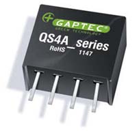
The QS4A series is specially designed for applications where a group of polar power supplies are isolated from the input power supply in a distributed power supply system on a circuit board. Features:
Field of application:
Download PCB Footprints and Schematic Symbols for free, to download/request, please click the Logo on the right in the below Selection Guide.
| |||||||||||||||||||||||||||||||||||||||||||||||||||||||||||||||||||||||||||||||||||||||||||||||||||||||||||||||||||||||||||||||||||||||||||||||||||||||||||||||||||||||||||||||||||||||||||||||||||||||||||||||||||||||||||||||||||||||||||||||||||||||||||||||||||||||||||||||||||||||||||||||||||||||||
| QD8E_1U | DIP8 | ±10% | 3.3; 5; 12; 15; 24 | 3.3; 5; 7,2; 9; 12; 15; 24 | 1 | 73% | -40°C - +85°C | QD8E_1U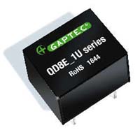
The QD8E_1U series is specially designed for applications where a group of polar power supplies are isolated from the input power supply in a distributed power supply system on a circuit board. Features:
Field of application:
Download PCB Footprints and Schematic Symbols for free, to download/request, please click the Logo on the right in the below Selection Guide.
| |||||||||||||||||||||||||||||||||||||||||||||||||||||||||||||||||||||||||||||||||||||||||||||||||||||||||||||||||||||||||||||||||||||||||||||||||||||||||||||||||||||||||||||||||||||||||||||||||||||||||||||||||||||||||||||||||||||||||||||||||||||||||||||||||||||||||||||||||||||||||||||||||||||||||||
| QD8E_3U | DIP8 | ±10% | 3.3; 5; 12; 15; 24 | 3.3; 5; 7,2; 9; 12; 15; 24 | 3 | 73% | -40°C - +85°C | QD8E_3U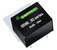
The QD8E_3U series is specially designed for applications where a group of polar power supplies are isolated from the input power supply in a distributed power supply system on a circuit board. Features:
Field of application:
Download PCB Footprints and Schematic Symbols for free, to download/request, please click the Logo on the right in the below Selection Guide.
| |||||||||||||||||||||||||||||||||||||||||||||||||||||||||||||||||||||||||||||||||||||||||||||||||||||||||||||||||||||||||||||||||||||||||||||||||||||||||||||||||||||||||||||||||||||||||||||||||||||||||||||||||||||||||||||||||||||||||||||||||||||||||||||||||||||||||||||||||||||||||||||||||||||||||||
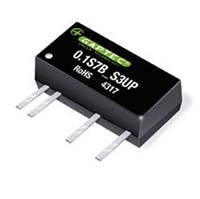
| QS7B_3UP | SIP7 | ±10% | 3.3; 5; 12; 15 | ±5 ±9; ±12; ±15; ±24 | 3 | • | 81% | -40°C - +105°C | QS7B_3UP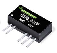
The QS7B_3UP series is specially designed for applications where a group of polar power supplies are isolated from the input power supply in a distributed power supply system on a circuit board. Features:
Field of application:
Download PCB Footprints and Schematic Symbols for free, to download/request, please click the Logo on the right in the below Selection Guide.
|
Series |
Case Size |
Input Range |
Input Voltage (VDC) |
Output Voltage (VDC) |
Output Current (A) |
Isolation (kVDC) |
Regulation |
SCP * |
η max. |
Operating Temp. |
Dimming |
Certs |
||||||||||||||||||||||||||||||||||||||||||||||||||||||||||||||||||||||||||||||||||||||||||||||||||||||||||||||||||||||||||||||||||||||||||||||||||||||||||||||||||||||||||||||||||||||||||||||||||||||||||||||||||||||||||||||||||||||||||||||||||||||||||||||||||||||||||||||||||||||||||||||||||||||||
| 0.5S4E_1U | SIP4 | ±10% | 3.3; 5; 12; 15; 24; 48 | 3.3; 5; 7.2; 9; 12; 15; 18; 24 | 1 | 79% | -40°C - +85°C | 0.5S4E_1U
The 0.5S4E_1U series is specially designed for applications where a group of polar power supplies are isolated from the input power supply in a distributed power supply system on a circuit board. Features:
Field of application:
Download PCB Footprints and Schematic Symbols for free, to download/request, please click the Logo on the right in the below Selection Guide.
| |||||||||||||||||||||||||||||||||||||||||||||||||||||||||||||||||||||||||||||||||||||||||||||||||||||||||||||||||||||||||||||||||||||||||||||||||||||||||||||||||||||||||||||||||||||||||||||||||||||||||||||||||||||||||||||||||||||||||||||||||||||||||||||||||||||||||||||||||||||||||||||||||||||||||||
| 0.5D8E_1U | DIP8 | ±10% | 3.3; 5; 12; 15; 24 | 3.3; 5; 7,2; 9; 12; 15; 18; 24 | 1 | 77% | -40°C - +85°C | 0.5D8E_1U
The 0.5D8E_1U series is specially designed for applications where a group of polar power supplies are isolated from the input power supply in a distributed power supply system on a circuit board. Features:
Field of application:
Download PCB Footprints and Schematic Symbols for free, to download/request, please click the Logo on the right in the below Selection Guide.
| |||||||||||||||||||||||||||||||||||||||||||||||||||||||||||||||||||||||||||||||||||||||||||||||||||||||||||||||||||||||||||||||||||||||||||||||||||||||||||||||||||||||||||||||||||||||||||||||||||||||||||||||||||||||||||||||||||||||||||||||||||||||||||||||||||||||||||||||||||||||||||||||||||||||||||
| 0.5T8E_1U | DIP8 | ±10% | 3.3; 5; 9; 12; 15 | 3.3; 5; 9; 12; 15 | 1 | 78% | -40°C - +85°C | 0.5T8E_1U
0.5T8E_1U SMD8 case series. Miniature surface mounted DC/DC Converters are a 0.5W low power and high efficiency DC/DC converters in SMD package, are an ideal and economical solution for many applications where noise reduction, voltage isolation, voltage conversion in distributed power systems is required. Features:
Download PCB Footprints and Schematic Symbols for free, to download/request, please click the Logo on the right in the below Selection Guide.
| |||||||||||||||||||||||||||||||||||||||||||||||||||||||||||||||||||||||||||||||||||||||||||||||||||||||||||||||||||||||||||||||||||||||||||||||||||||||||||||||||||||||||||||||||||||||||||||||||||||||||||||||||||||||||||||||||||||||||||||||||||||||||||||||||||||||||||||||||||||||||||||||||||||||||||
| 0.5S4E_3U | SIP4 | ±10% | 3.3; 5; 12; 15; 24; 48 | 3.3; 5; 7.2; 9; 12; 15; 18; 24 | 3 | 83% | -40°C - +85°C | 0.5S4E_3U
The 0.5S4E_3U series is specially designed for applications where a group of polar power supplies are isolated from the input power supply in a distributed power supply system on a circuit board. Features:
Field of application:
Download PCB Footprints and Schematic Symbols for free, to download/request, please click the Logo on the right in the below Selection Guide.
| |||||||||||||||||||||||||||||||||||||||||||||||||||||||||||||||||||||||||||||||||||||||||||||||||||||||||||||||||||||||||||||||||||||||||||||||||||||||||||||||||||||||||||||||||||||||||||||||||||||||||||||||||||||||||||||||||||||||||||||||||||||||||||||||||||||||||||||||||||||||||||||||||||||||||||
| 0.5D8E_3U | DIP8 | ±10% | 3.3; 5; 12; 15 | 3.3; 5; 7,2; 9; 12; 15; 18; 24 | 1 | 77% | -40°C - +85°C | 0.5D8E_3U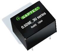
The 0.5D8E_3U series is specially designed for applications where a group of polar power supplies are isolated from the input power supply in a distributed power supply system on a circuit board. Features:
Field of application:
Download PCB Footprints and Schematic Symbols for free, to download/request, please click the Logo on the right in the below Selection Guide.
| |||||||||||||||||||||||||||||||||||||||||||||||||||||||||||||||||||||||||||||||||||||||||||||||||||||||||||||||||||||||||||||||||||||||||||||||||||||||||||||||||||||||||||||||||||||||||||||||||||||||||||||||||||||||||||||||||||||||||||||||||||||||||||||||||||||||||||||||||||||||||||||||||||||||||||
| 0.5S7B_3UP | SIP7 | ±10% | 3.3; 5; 12; 15 | 3.3; 5; 9; 12; 15; 24; ±5 ±9; ±12; ±15 | 3 | • | 83% | -40°C - +105°C | 0.5S7B_3UP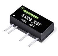
The 0.5S7B_3UP series is specially designed for applications where a group of polar power supplies are isolated from the input power supply in a distributed power supply system on a circuit board. Features:
Field of application:
Download PCB Footprints and Schematic Symbols for free, to download/request, please click the Logo on the right in the below Selection Guide.
| ||||||||||||||||||||||||||||||||||||||||||||||||||||||||||||||||||||||||||||||||||||||||||||||||||||||||||||||||||||||||||||||||||||||||||||||||||||||||||||||||||||||||||||||||||||||||||||||||||||||||||||||||||||||||||||||||||||||||||||||||||||||||||||||||||||||||||||||||||||||||||||||||||||||||||
| 0.5D14B_3UP | DIP14 | ±10% | 3.3; 5; 12 | 3.3; 5; 9; 12; 15; ±5 ±9; ±12; ±15 | 3 | • | 80% | -40°C - +105°C | 0.5D14B_3UP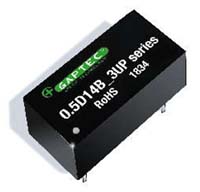
The 0.5D14B_3UP series is specially designed for applications where a group of polar power supplies are isolated from the input power supply in a distributed power supply system on a circuit board. Features:
Field of application:
Download PCB Footprints and Schematic Symbols for free, to download/request, please click the Logo on the right in the below Selection Guide.
|
Series |
Case Size |
Input Range |
Input Voltage (VDC) |
Output Voltage (VDC) |
Output Current (A) |
Isolation (kVDC) |
Regulation |
SCP * |
η max. |
Operating Temp. |
Dimming |
Certs |
||||||||||||||||||||||||||||||||||||||||||||||||||||||||||||||||||||||||||||||||||||||||||||||||||||||||||||||||||||||||||||||||||||||||||||||||||||||||||||||||||||||||||||||||||||||||||||||||||||||||
| 0.75S4A_3RP | SIP4 | ±10% | 5 | 3.3; 5; 9; 12; 15 | 3 | • | • | 74% | -40°C - +85°C | UL62368 | 0.75S4A_3RP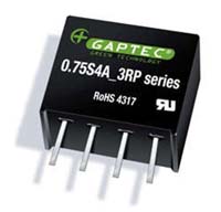
The 0.75S4A_3RP series is specially designed for applications where a group of polar power supplies are isolated from the input power supply in a distributed power supply system on a circuit board. Features:
Field of application:
Download PCB Footprints and Schematic Symbols for free, to download/request, please click the Logo on the right in the below Selection Guide.
| ||||||||||||||||||||||||||||||||||||||||||||||||||||||||||||||||||||||||||||||||||||||||||||||||||||||||||||||||||||||||||||||||||||||||||||||||||||||||||||||||||||||||||||||||||||||||||||||||||||||||
| 0.75S7A_1U | SIP7 | ±10% | 5; 12; 24; 48 | 3.3; 5; 7.2; 9; 12; 15; 18; 24; ±3.3; ±5; ±7.2; ±9; ±12; ±15; ±18; ±24 | 1 | 80% | -40°C - +85°C | 0.75S7A_1U
The 0.75S7A_1U series is specially designed for applications where a group of polar power supplies are isolated from the input power supply in a distributed power supply system on a circuit board. Features:
Field of application:
Download PCB Footprints and Schematic Symbols for free, to download/request, please click the Logo on the right in the below Selection Guide.
|
Series |
Case Size |
Input Range |
Input Voltage (VDC) |
Output Voltage (VDC) |
Output Current (A) |
Isolation (kVDC) |
Regulation |
SCP * |
η max. |
Operating Temp. |
Dimming |
Certs |
||||||||||||||||||||||||||||||||||||||||||||||||||||||||||||||||||||||||||||||||||||||||||||||||||||||||||||||||||||||||||||||||||||||||||||||||||||||||||||||||||||||||||||||||||||||||||||||||||||||||||||||||||||||||||||||||||||||||||||||||||||||||||||||||||||||||||||||||||||||||||||||||||||||||||||||||||||||||||||||||||||||||||||||||||||||||||||||||||||||||||||||||||||||||||||||||||||||||||||||||||||||||||||||||||||||||||||||||||||||||||||||||||||||||||||||||||||||||||||||||||||||||||||||||||||||||||||||||||||||||||||||||||||||||||||||||||||||||||||||||||||||||||||||||||
| 1S4E_1U | SIP4 | ±10% | 3.3; 5; 12; 15; 24; 48 | 3.3; 5; 7.2; 9; 12; 15;18; 24 | 1 | 83% | -40°C - +85°C | 1S4E_1U
The 1S4E_1U cost effective series are specially designed for applications where a single power supply is isolated from the input power supply in a distributed power supply system on a circuit board.
Download PCB Footprints and Schematic Symbols for free, to download/request, please click the Logo on the right in the below Selection Guide.
| |||||||||||||||||||||||||||||||||||||||||||||||||||||||||||||||||||||||||||||||||||||||||||||||||||||||||||||||||||||||||||||||||||||||||||||||||||||||||||||||||||||||||||||||||||||||||||||||||||||||||||||||||||||||||||||||||||||||||||||||||||||||||||||||||||||||||||||||||||||||||||||||||||||||||||||||||||||||||||||||||||||||||||||||||||||||||||||||||||||||||||||||||||||||||||||||||||||||||||||||||||||||||||||||||||||||||||||||||||||||||||||||||||||||||||||||||||||||||||||||||||||||||||||||||||||||||||||||||||||||||||||||||||||||||||||||||||||||||||||||||||||||||||||||||||||
| 1S4A_1.5UP | SIP4 | ±10% | 3.3; 5; 12; 15; 24 | 3.3; 5; 9; 12; 15; 24 | 1.5 | • | 83% | -40°C - +105°C | UL60950 | 1S4A_1.5UP
The 1S4A Series are designed for applications where isolated output is required from a distributed power system. Features:
Field of application:
Download PCB Footprints and Schematic Symbols for free, to download/request, please click the Logo on the right in the below Selection Guide.
| |||||||||||||||||||||||||||||||||||||||||||||||||||||||||||||||||||||||||||||||||||||||||||||||||||||||||||||||||||||||||||||||||||||||||||||||||||||||||||||||||||||||||||||||||||||||||||||||||||||||||||||||||||||||||||||||||||||||||||||||||||||||||||||||||||||||||||||||||||||||||||||||||||||||||||||||||||||||||||||||||||||||||||||||||||||||||||||||||||||||||||||||||||||||||||||||||||||||||||||||||||||||||||||||||||||||||||||||||||||||||||||||||||||||||||||||||||||||||||||||||||||||||||||||||||||||||||||||||||||||||||||||||||||||||||||||||||||||||||||||||||||||||||||||||||
| 1MS4A_1U | SIP4 Micro | ±10% | 3.3; 5; 12 | 3; 5; 9; 12; 15 | 1 | 78% | -40°C - +85°C | 1MS4A_1U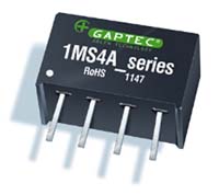
The 1MS4A Series are specially designed for applications where a single power supply is isolated from the input power supply in a distributed power supply system on a circuit board. Features:
Field of application:
Download PCB Footprints and Schematic Symbols for free, to download/request, please click the Logo on the right in the below Selection Guide.
| |||||||||||||||||||||||||||||||||||||||||||||||||||||||||||||||||||||||||||||||||||||||||||||||||||||||||||||||||||||||||||||||||||||||||||||||||||||||||||||||||||||||||||||||||||||||||||||||||||||||||||||||||||||||||||||||||||||||||||||||||||||||||||||||||||||||||||||||||||||||||||||||||||||||||||||||||||||||||||||||||||||||||||||||||||||||||||||||||||||||||||||||||||||||||||||||||||||||||||||||||||||||||||||||||||||||||||||||||||||||||||||||||||||||||||||||||||||||||||||||||||||||||||||||||||||||||||||||||||||||||||||||||||||||||||||||||||||||||||||||||||||||||||||||||||||
| 1MS4A_3UP | SIP4 Micro | ±10% | 3.3; 5; 12; 24 | 3; 5; 9; 12; 15 | 3 | • | 81% | -40°C - +85°C | 1MS4A_3UP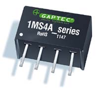
The 1MS4A_P Series are specially designed for applications where a single power supply is isolated from the input power supply in a distributed power supply system on a circuit board. Features:
Field of application:
Download PCB Footprints and Schematic Symbols for free, to download/request, please click the Logo on the right in the below Selection Guide.
| ||||||||||||||||||||||||||||||||||||||||||||||||||||||||||||||||||||||||||||||||||||||||||||||||||||||||||||||||||||||||||||||||||||||||||||||||||||||||||||||||||||||||||||||||||||||||||||||||||||||||||||||||||||||||||||||||||||||||||||||||||||||||||||||||||||||||||||||||||||||||||||||||||||||||||||||||||||||||||||||||||||||||||||||||||||||||||||||||||||||||||||||||||||||||||||||||||||||||||||||||||||||||||||||||||||||||||||||||||||||||||||||||||||||||||||||||||||||||||||||||||||||||||||||||||||||||||||||||||||||||||||||||||||||||||||||||||||||||||||||||||||||||||||||||||||
| 1D8E_1U | DIP8 | ±10% | 3.3; 5; 12; 15; 24; 48 | 3.3; 5; 7,2; 9; 12; 15; 18; 24 | 1 | 83% | -40°C - +85°C | 1D8E_1U
The 1D8E_1U Series are designed for applications where isolated output is required from a distributed power system. Features:
Download PCB Footprints and Schematic Symbols for free, to download/request, please click the Logo on the right in the below Selection Guide.
| |||||||||||||||||||||||||||||||||||||||||||||||||||||||||||||||||||||||||||||||||||||||||||||||||||||||||||||||||||||||||||||||||||||||||||||||||||||||||||||||||||||||||||||||||||||||||||||||||||||||||||||||||||||||||||||||||||||||||||||||||||||||||||||||||||||||||||||||||||||||||||||||||||||||||||||||||||||||||||||||||||||||||||||||||||||||||||||||||||||||||||||||||||||||||||||||||||||||||||||||||||||||||||||||||||||||||||||||||||||||||||||||||||||||||||||||||||||||||||||||||||||||||||||||||||||||||||||||||||||||||||||||||||||||||||||||||||||||||||||||||||||||||||||||||||||
| 1D8E_3U | DIP8 | ±10% | 3.3; 5; 12; 15; 24 | 3.3; 5; 7,2; 9; 12; 15; 18; 24 | 3 | 83% | -40°C - +85°C | 1D8E_3U
The 1D8E_3 Series are designed for applications where isolated output is required from a distributed power system. Features:
Download PCB Footprints and Schematic Symbols for free, to download/request, please click the Logo on the right in the below Selection Guide.
| |||||||||||||||||||||||||||||||||||||||||||||||||||||||||||||||||||||||||||||||||||||||||||||||||||||||||||||||||||||||||||||||||||||||||||||||||||||||||||||||||||||||||||||||||||||||||||||||||||||||||||||||||||||||||||||||||||||||||||||||||||||||||||||||||||||||||||||||||||||||||||||||||||||||||||||||||||||||||||||||||||||||||||||||||||||||||||||||||||||||||||||||||||||||||||||||||||||||||||||||||||||||||||||||||||||||||||||||||||||||||||||||||||||||||||||||||||||||||||||||||||||||||||||||||||||||||||||||||||||||||||||||||||||||||||||||||||||||||||||||||||||||||||||||||||||
| 1S7AE_DS1U | SIP7 | ±10% | 5; 12; 24 | Vout1: 3.3; 5; 7,2; 9; 12; 15 Vout2: 3.3; 5; 7,2; 9; 12; 15 | 1 | 80% | -40°C - +85°C | 1S7AE_DS1U
The 1S7AE_DS1U Series are specially designed for applications where a group of polar power supplies are isolated from the input power supply in a distributed power supply system on a circuit board. Features:
Download PCB Footprints and Schematic Symbols for free, to download/request, please click the Logo on the right in the below Selection Guide.
| |||||||||||||||||||||||||||||||||||||||||||||||||||||||||||||||||||||||||||||||||||||||||||||||||||||||||||||||||||||||||||||||||||||||||||||||||||||||||||||||||||||||||||||||||||||||||||||||||||||||||||||||||||||||||||||||||||||||||||||||||||||||||||||||||||||||||||||||||||||||||||||||||||||||||||||||||||||||||||||||||||||||||||||||||||||||||||||||||||||||||||||||||||||||||||||||||||||||||||||||||||||||||||||||||||||||||||||||||||||||||||||||||||||||||||||||||||||||||||||||||||||||||||||||||||||||||||||||||||||||||||||||||||||||||||||||||||||||||||||||||||||||||||||||||||||
| 1D8A_1.5UP | DIP8 | ±10% | 3.3; 5; 12; 15; 24 | 3.3; 5; 9; 12; 15; 24 | 1.5 | • | 83% | -40°C - +105°C | UL60950 | 1D8A_1.5UP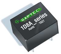
The 1D8A Series are designed for applications where isolated output is required from a distributed power system. Features:
Field of application:
Download PCB Footprints and Schematic Symbols for free, to download/request, please click the Logo on the right in the below Selection Guide.
| |||||||||||||||||||||||||||||||||||||||||||||||||||||||||||||||||||||||||||||||||||||||||||||||||||||||||||||||||||||||||||||||||||||||||||||||||||||||||||||||||||||||||||||||||||||||||||||||||||||||||||||||||||||||||||||||||||||||||||||||||||||||||||||||||||||||||||||||||||||||||||||||||||||||||||||||||||||||||||||||||||||||||||||||||||||||||||||||||||||||||||||||||||||||||||||||||||||||||||||||||||||||||||||||||||||||||||||||||||||||||||||||||||||||||||||||||||||||||||||||||||||||||||||||||||||||||||||||||||||||||||||||||||||||||||||||||||||||||||||||||||||||||||||||||||
| 1MD8A_3UP | DIP8 Micro | ±10% | 3.3; 5; 9; 12; 24 | 3.3; 5; 9; 12; 15 | 3 | • | 81% | -40°C - +85°C | 1MD8A_3UP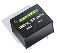
The 1MD8A_3UP series are specially designed for applications where a group of polar power supplies are isolated from the input power supply in a distributed power supply system on a circuit board. Features:
Field of application:
Download PCB Footprints and Schematic Symbols for free, to download/request, please click the Logo on the right in the below Selection Guide.
| ||||||||||||||||||||||||||||||||||||||||||||||||||||||||||||||||||||||||||||||||||||||||||||||||||||||||||||||||||||||||||||||||||||||||||||||||||||||||||||||||||||||||||||||||||||||||||||||||||||||||||||||||||||||||||||||||||||||||||||||||||||||||||||||||||||||||||||||||||||||||||||||||||||||||||||||||||||||||||||||||||||||||||||||||||||||||||||||||||||||||||||||||||||||||||||||||||||||||||||||||||||||||||||||||||||||||||||||||||||||||||||||||||||||||||||||||||||||||||||||||||||||||||||||||||||||||||||||||||||||||||||||||||||||||||||||||||||||||||||||||||||||||||||||||||||
| 1D8W_1.5RP | DIP | 2:1 | 9-18; 18-36 | 3.3; 5; 12; 15; 24 | 1.5 | • | • | 80% | -40°C - +85°C | UL62368 | 1D8W_1.5RP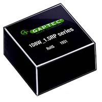
The 1D8W_1.5RP Series is specially designed for applications where a wide range input voltage power supplies are isolated from the input power supply in a distributed power supply system on a circuit board. Features:
Field of application:
Download PCB Footprints and Schematic Symbols for free, to download/request, please click the Logo on the right in the below Selection Guide.
| ||||||||||||||||||||||||||||||||||||||||||||||||||||||||||||||||||||||||||||||||||||||||||||||||||||||||||||||||||||||||||||||||||||||||||||||||||||||||||||||||||||||||||||||||||||||||||||||||||||||||||||||||||||||||||||||||||||||||||||||||||||||||||||||||||||||||||||||||||||||||||||||||||||||||||||||||||||||||||||||||||||||||||||||||||||||||||||||||||||||||||||||||||||||||||||||||||||||||||||||||||||||||||||||||||||||||||||||||||||||||||||||||||||||||||||||||||||||||||||||||||||||||||||||||||||||||||||||||||||||||||||||||||||||||||||||||||||||||||||||||||||||||||||||||||
| 1D14A_DS3UP | DIP14 | ±10% | 5; 12 | Vout1: 5 Vout2: 3.3; 5; 9; 12; 15 | 3 | • | 80% | -40°C - +85°C | 1D14A_DS3UP
The 1D14A_DS3UP Series are specially designed for applications where a group of polar power supplies are isolated from the input power supply in a distributed power supply system on a circuit board. Features:
Download PCB Footprints and Schematic Symbols for free, to download/request, please click the Logo on the right in the below Selection Guide.
| ||||||||||||||||||||||||||||||||||||||||||||||||||||||||||||||||||||||||||||||||||||||||||||||||||||||||||||||||||||||||||||||||||||||||||||||||||||||||||||||||||||||||||||||||||||||||||||||||||||||||||||||||||||||||||||||||||||||||||||||||||||||||||||||||||||||||||||||||||||||||||||||||||||||||||||||||||||||||||||||||||||||||||||||||||||||||||||||||||||||||||||||||||||||||||||||||||||||||||||||||||||||||||||||||||||||||||||||||||||||||||||||||||||||||||||||||||||||||||||||||||||||||||||||||||||||||||||||||||||||||||||||||||||||||||||||||||||||||||||||||||||||||||||||||||||
| 1D14B_1.5UP | DIP14 | ±10% | 5; 12; 24 | ±5; ±9; ±12; ±15; ±24 | 1.5 | • | 81% | -40°C - +105°C | UL60950 | 1D14B_1.5UP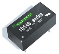
The 1D14B series is specially designed for applications where an isolated voltage is required in a distributed power supply system. Features:
Field of application:
Download PCB Footprints and Schematic Symbols for free, to download/request, please click the Logo on the right in the below Selection Guide.
| |||||||||||||||||||||||||||||||||||||||||||||||||||||||||||||||||||||||||||||||||||||||||||||||||||||||||||||||||||||||||||||||||||||||||||||||||||||||||||||||||||||||||||||||||||||||||||||||||||||||||||||||||||||||||||||||||||||||||||||||||||||||||||||||||||||||||||||||||||||||||||||||||||||||||||||||||||||||||||||||||||||||||||||||||||||||||||||||||||||||||||||||||||||||||||||||||||||||||||||||||||||||||||||||||||||||||||||||||||||||||||||||||||||||||||||||||||||||||||||||||||||||||||||||||||||||||||||||||||||||||||||||||||||||||||||||||||||||||||||||||||||||||||||||||||
| 1D14C_3UP | DIP14 | ±10% | 3.3; 5; 12; 15; 24 | 3.3; 5; 12; 15; ±5; ±12; ±15 | 3 | • | 81% | -40°C - +105°C | UL60950 | 1D14C_3UP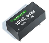
The 1D14B series is specially designed for applications where an isolated voltage is required in a distributed power supply system. Features:
Field of application:
Download PCB Footprints and Schematic Symbols for free, to download/request, please click the Logo on the right in the below Selection Guide.
| |||||||||||||||||||||||||||||||||||||||||||||||||||||||||||||||||||||||||||||||||||||||||||||||||||||||||||||||||||||||||||||||||||||||||||||||||||||||||||||||||||||||||||||||||||||||||||||||||||||||||||||||||||||||||||||||||||||||||||||||||||||||||||||||||||||||||||||||||||||||||||||||||||||||||||||||||||||||||||||||||||||||||||||||||||||||||||||||||||||||||||||||||||||||||||||||||||||||||||||||||||||||||||||||||||||||||||||||||||||||||||||||||||||||||||||||||||||||||||||||||||||||||||||||||||||||||||||||||||||||||||||||||||||||||||||||||||||||||||||||||||||||||||||||||||
| 1S7A_DS1U | SIP7 | ±10% | 5; 9; 12; 15; 24 | Vout1: 3.3; 5; 9; 12; 15; 24 Vout2: 3.3; 5; 9; 12; 15; 24 | 1 | 80% | -40°C - +85°C | 1S7A_DS1U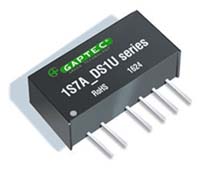
The 1S7A_DS1U Series are specially designed for applications where a group of polar power supplies are isolated from the input power supply in a distributed power supply system on a circuit board. Features:
Download PCB Footprints and Schematic Symbols for free, to download/request, please click the Logo on the right in the below Selection Guide.
| |||||||||||||||||||||||||||||||||||||||||||||||||||||||||||||||||||||||||||||||||||||||||||||||||||||||||||||||||||||||||||||||||||||||||||||||||||||||||||||||||||||||||||||||||||||||||||||||||||||||||||||||||||||||||||||||||||||||||||||||||||||||||||||||||||||||||||||||||||||||||||||||||||||||||||||||||||||||||||||||||||||||||||||||||||||||||||||||||||||||||||||||||||||||||||||||||||||||||||||||||||||||||||||||||||||||||||||||||||||||||||||||||||||||||||||||||||||||||||||||||||||||||||||||||||||||||||||||||||||||||||||||||||||||||||||||||||||||||||||||||||||||||||||||||||||
| 1S7A_DS3UP | SIP7 | ±10% | 5; 9; 12; 15; 24 | Vout1: 3.3; 5; 9; 12; 15; 24 Vout2: 3.3; 5; 9; 12; 15; 24 | 3 | • | 80% | -40°C - +85°C | 1S7A_DS3UP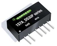
The 1S7A_DS3UP Series are specially designed for applications where a group of polar power supplies are isolated from the input power supply in a distributed power supply system on a circuit board. Features:
Download PCB Footprints and Schematic Symbols for free, to download/request, please click the Logo on the right in the below Selection Guide.
| ||||||||||||||||||||||||||||||||||||||||||||||||||||||||||||||||||||||||||||||||||||||||||||||||||||||||||||||||||||||||||||||||||||||||||||||||||||||||||||||||||||||||||||||||||||||||||||||||||||||||||||||||||||||||||||||||||||||||||||||||||||||||||||||||||||||||||||||||||||||||||||||||||||||||||||||||||||||||||||||||||||||||||||||||||||||||||||||||||||||||||||||||||||||||||||||||||||||||||||||||||||||||||||||||||||||||||||||||||||||||||||||||||||||||||||||||||||||||||||||||||||||||||||||||||||||||||||||||||||||||||||||||||||||||||||||||||||||||||||||||||||||||||||||||||||
| 1S7AE_1U | SIP7 | ±10% | 3,3; 5; 12; 15; 24; 48 | 3.3; 5; 9; 12; 15; 18; 24; ±3,3; ±5; ±7.2; ±9; ±12; ±15; ±24 | 1 | 86% | -40°C - +85°C | 1S7AE_1U
The 1S7AE_1U Series are specially designed for cost effective applications where a group of polar power supplies are isolated from the input power supply in a distributed power supply system on a circuit board. Features:
Field of application:
Download PCB Footprints and Schematic Symbols for free, to download/request, please click the Logo on the right in the below Selection Guide.
| |||||||||||||||||||||||||||||||||||||||||||||||||||||||||||||||||||||||||||||||||||||||||||||||||||||||||||||||||||||||||||||||||||||||||||||||||||||||||||||||||||||||||||||||||||||||||||||||||||||||||||||||||||||||||||||||||||||||||||||||||||||||||||||||||||||||||||||||||||||||||||||||||||||||||||||||||||||||||||||||||||||||||||||||||||||||||||||||||||||||||||||||||||||||||||||||||||||||||||||||||||||||||||||||||||||||||||||||||||||||||||||||||||||||||||||||||||||||||||||||||||||||||||||||||||||||||||||||||||||||||||||||||||||||||||||||||||||||||||||||||||||||||||||||||||||
| 1S7E_1.5UP | SIP7 | ±10% | 3.3; 5; 12; 15; 24 | 3.3; 5; 9; 12; 15; 24; ±3.3; ±5; ±12; ±15; ±24 | 1.5 | • | 80% | -40°C - +105°C | UL60950 | 1S7E_1.5UP
The 1S7E Series are specially designed for applications where a group of polar power supplies are isolated from the input power supply in a distributed power supply system on a circuit board. Features:
Field of application:
Download PCB Footprints and Schematic Symbols for free, to download/request, please click the Logo on the right in the below Selection Guide.
| |||||||||||||||||||||||||||||||||||||||||||||||||||||||||||||||||||||||||||||||||||||||||||||||||||||||||||||||||||||||||||||||||||||||||||||||||||||||||||||||||||||||||||||||||||||||||||||||||||||||||||||||||||||||||||||||||||||||||||||||||||||||||||||||||||||||||||||||||||||||||||||||||||||||||||||||||||||||||||||||||||||||||||||||||||||||||||||||||||||||||||||||||||||||||||||||||||||||||||||||||||||||||||||||||||||||||||||||||||||||||||||||||||||||||||||||||||||||||||||||||||||||||||||||||||||||||||||||||||||||||||||||||||||||||||||||||||||||||||||||||||||||||||||||||||
| 1S7A_1.5UP | SIP7 | ±10% | 5 | 5; 9; 12; 15; ±5; ±9; ±12; ±15 | 1.5 | • | 83% | -40°C - +105°C | UL62368 | 1S7A_1.5UP
The 1S7A Series are specially designed for applications where a group of polar power supplies are isolated from the input power supply in a distributed power supply system on a circuit board. Features:
Field of application:
Download PCB Footprints and Schematic Symbols for free, to download/request, please click the Logo on the right in the below Selection Guide.
| |||||||||||||||||||||||||||||||||||||||||||||||||||||||||||||||||||||||||||||||||||||||||||||||||||||||||||||||||||||||||||||||||||||||||||||||||||||||||||||||||||||||||||||||||||||||||||||||||||||||||||||||||||||||||||||||||||||||||||||||||||||||||||||||||||||||||||||||||||||||||||||||||||||||||||||||||||||||||||||||||||||||||||||||||||||||||||||||||||||||||||||||||||||||||||||||||||||||||||||||||||||||||||||||||||||||||||||||||||||||||||||||||||||||||||||||||||||||||||||||||||||||||||||||||||||||||||||||||||||||||||||||||||||||||||||||||||||||||||||||||||||||||||||||||||
| 1S7B_3UP | SIP7 | ±10% | 5 | 3.3; 5; 9; 12; 15; 24; ±5; ±9; ±12; ±15; ±24 | 3 | • | -40°C - +105°C | UL62368 | 1S7B_3UP
The 1S7B_3UP series is specially designed for applications where an isolated voltage is required in a distributed power supply system. Features:
Download PCB Footprints and Schematic Symbols for free, to download/request, please click the Logo on the right in the below Selection Guide.
| ||||||||||||||||||||||||||||||||||||||||||||||||||||||||||||||||||||||||||||||||||||||||||||||||||||||||||||||||||||||||||||||||||||||||||||||||||||||||||||||||||||||||||||||||||||||||||||||||||||||||||||||||||||||||||||||||||||||||||||||||||||||||||||||||||||||||||||||||||||||||||||||||||||||||||||||||||||||||||||||||||||||||||||||||||||||||||||||||||||||||||||||||||||||||||||||||||||||||||||||||||||||||||||||||||||||||||||||||||||||||||||||||||||||||||||||||||||||||||||||||||||||||||||||||||||||||||||||||||||||||||||||||||||||||||||||||||||||||||||||||||||||||||||||||||||
| 1S7B_4UP | SIP7 | ±10% | 3.3; 5; 9; 12; 15; 24 | 3.3; 5; 9; 12; 15; 24; ±5; ±9; ±12; ±15; ±24 | 4 | • | 80% | -40°C - +105°C | 1S7B_4UP
The 1S7B_4UP series is specially designed for applications where an isolated voltage is required in a distributed power supply system. Features:
Download PCB Footprints and Schematic Symbols for free, to download/request, please click the Logo on the right in the below Selection Guide.
| ||||||||||||||||||||||||||||||||||||||||||||||||||||||||||||||||||||||||||||||||||||||||||||||||||||||||||||||||||||||||||||||||||||||||||||||||||||||||||||||||||||||||||||||||||||||||||||||||||||||||||||||||||||||||||||||||||||||||||||||||||||||||||||||||||||||||||||||||||||||||||||||||||||||||||||||||||||||||||||||||||||||||||||||||||||||||||||||||||||||||||||||||||||||||||||||||||||||||||||||||||||||||||||||||||||||||||||||||||||||||||||||||||||||||||||||||||||||||||||||||||||||||||||||||||||||||||||||||||||||||||||||||||||||||||||||||||||||||||||||||||||||||||||||||||||
| 1S7B_6U | SIP7 | ±10% | 5; 9; 12; 15; 24 | 5; 9; 12; 15; 24; ±5; ±9; ±12; ±15; ±24 | 6 | 80% | -40°C - +85°C | 1S7B_6U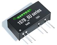
The 1S7B_6U series is specially designed for applications where an isolated voltage is required in a distributed power supply system. Features:
Field Application:
Download PCB Footprints and Schematic Symbols for free, to download/request, please click the Logo on the right in the below Selection Guide.
| |||||||||||||||||||||||||||||||||||||||||||||||||||||||||||||||||||||||||||||||||||||||||||||||||||||||||||||||||||||||||||||||||||||||||||||||||||||||||||||||||||||||||||||||||||||||||||||||||||||||||||||||||||||||||||||||||||||||||||||||||||||||||||||||||||||||||||||||||||||||||||||||||||||||||||||||||||||||||||||||||||||||||||||||||||||||||||||||||||||||||||||||||||||||||||||||||||||||||||||||||||||||||||||||||||||||||||||||||||||||||||||||||||||||||||||||||||||||||||||||||||||||||||||||||||||||||||||||||||||||||||||||||||||||||||||||||||||||||||||||||||||||||||||||||||||
| 1S7B_6UP | SIP7 | ±10% | 5; 12; 15; 24 | 3.3; 5; 12; 24; ±5; ±7.2; ±9; ±12; ±15 | 6 | • | 82% | -40°C - +105°C | UL60601 | 1S7B_6UP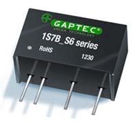
The 1S7B_6UP series meet reinforced insulation requirements. It is specially designed for applications which require compact size, high isolation, low isolation capacitor and low leakage current power. Features:
Field of application:
Download PCB Footprints and Schematic Symbols for free, to download/request, please click the Logo on the right in the below Selection Guide.
| |||||||||||||||||||||||||||||||||||||||||||||||||||||||||||||||||||||||||||||||||||||||||||||||||||||||||||||||||||||||||||||||||||||||||||||||||||||||||||||||||||||||||||||||||||||||||||||||||||||||||||||||||||||||||||||||||||||||||||||||||||||||||||||||||||||||||||||||||||||||||||||||||||||||||||||||||||||||||||||||||||||||||||||||||||||||||||||||||||||||||||||||||||||||||||||||||||||||||||||||||||||||||||||||||||||||||||||||||||||||||||||||||||||||||||||||||||||||||||||||||||||||||||||||||||||||||||||||||||||||||||||||||||||||||||||||||||||||||||||||||||||||||||||||||||
| 1S7A_1RP | SIP7 | ±10% | 5; 12; 15; 24 | 3.3; 5; 9; 12; 15; 24 | 1 | • | • | 75% | -40°C - +85°C | 1S7A_1RP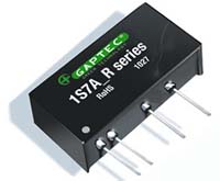
The 1S7A Series is specially designed for applications where a single power supply is highly isolated from the input power supply in a distributed power supply system on a circuit board. Features:
Field of application:
Download PCB Footprints and Schematic Symbols for free, to download/request, please click the Logo on the right in the below Selection Guide.
| |||||||||||||||||||||||||||||||||||||||||||||||||||||||||||||||||||||||||||||||||||||||||||||||||||||||||||||||||||||||||||||||||||||||||||||||||||||||||||||||||||||||||||||||||||||||||||||||||||||||||||||||||||||||||||||||||||||||||||||||||||||||||||||||||||||||||||||||||||||||||||||||||||||||||||||||||||||||||||||||||||||||||||||||||||||||||||||||||||||||||||||||||||||||||||||||||||||||||||||||||||||||||||||||||||||||||||||||||||||||||||||||||||||||||||||||||||||||||||||||||||||||||||||||||||||||||||||||||||||||||||||||||||||||||||||||||||||||||||||||||||||||||||||||||||
| 1S7BE_3RP | SIP7 | ±10% | 3.3; 5; 12; 24 | 3.3; 5; 7,2; 9; 12; 15 | 3 | • | • | 71% | -40°C - +85°C | 1S7BE_3RP
The 1S7BE_3RP Series is specially designed for applications where a single power supply is highly isolated from the input power supply in a distributed power supply system on a circuit board. Features:
Field of application:
Download PCB Footprints and Schematic Symbols for free, to download/request, please click the Logo on the right in the below Selection Guide.
| |||||||||||||||||||||||||||||||||||||||||||||||||||||||||||||||||||||||||||||||||||||||||||||||||||||||||||||||||||||||||||||||||||||||||||||||||||||||||||||||||||||||||||||||||||||||||||||||||||||||||||||||||||||||||||||||||||||||||||||||||||||||||||||||||||||||||||||||||||||||||||||||||||||||||||||||||||||||||||||||||||||||||||||||||||||||||||||||||||||||||||||||||||||||||||||||||||||||||||||||||||||||||||||||||||||||||||||||||||||||||||||||||||||||||||||||||||||||||||||||||||||||||||||||||||||||||||||||||||||||||||||||||||||||||||||||||||||||||||||||||||||||||||||||||||
| 1S7WA_3RP | SIP7 | 2:1 | 4.5-9; 9-18; 18-36 | 5; 9; 12; 15; 24 | 3 | • | • | 83% | -40°C - +95°C | 1S7WA_3RP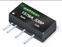
The 1S7WA Series are specially designed for applications where a group of polar power supplies are isolated from the input power supply in a distributed power supply system on a circuit board. Features:
Download PCB Footprints and Schematic Symbols for free, to download/request, please click the Logo on the right in the below Selection Guide.
| |||||||||||||||||||||||||||||||||||||||||||||||||||||||||||||||||||||||||||||||||||||||||||||||||||||||||||||||||||||||||||||||||||||||||||||||||||||||||||||||||||||||||||||||||||||||||||||||||||||||||||||||||||||||||||||||||||||||||||||||||||||||||||||||||||||||||||||||||||||||||||||||||||||||||||||||||||||||||||||||||||||||||||||||||||||||||||||||||||||||||||||||||||||||||||||||||||||||||||||||||||||||||||||||||||||||||||||||||||||||||||||||||||||||||||||||||||||||||||||||||||||||||||||||||||||||||||||||||||||||||||||||||||||||||||||||||||||||||||||||||||||||||||||||||||
| 1S7WB_3RP | SIP7 | 2:1 | 4.5-9; 9-18; 18-36 | 5; 9; 12; 15; 24 | 3 | • | • | 83% | -40°C - +95°C | 1S7WB_3RP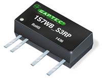
The 1S7WB Series are specially designed for applications where a group of polar power supplies are isolated from the input power supply in a distributed power supply system on a circuit board. Features:
Download PCB Footprints and Schematic Symbols for free, to download/request, please click the Logo on the right in the below Selection Guide.
| |||||||||||||||||||||||||||||||||||||||||||||||||||||||||||||||||||||||||||||||||||||||||||||||||||||||||||||||||||||||||||||||||||||||||||||||||||||||||||||||||||||||||||||||||||||||||||||||||||||||||||||||||||||||||||||||||||||||||||||||||||||||||||||||||||||||||||||||||||||||||||||||||||||||||||||||||||||||||||||||||||||||||||||||||||||||||||||||||||||||||||||||||||||||||||||||||||||||||||||||||||||||||||||||||||||||||||||||||||||||||||||||||||||||||||||||||||||||||||||||||||||||||||||||||||||||||||||||||||||||||||||||||||||||||||||||||||||||||||||||||||||||||||||||||||
| 1S8W_1.5RP | SIP8 | 2:1 | 4.5-9; 9-18; 18-36; 36-75 | 5; 9; 12; 15; 24; ±5; ±12; ±15 | 1.5 | • | • | 79% | -40°C - +85°C | UL60950 | 1S8W_1.5RP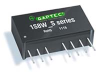
The 1S8W_1.5 series are specially designed for applications where a wide range input voltage power supplies are isolated from the input power supply in a distributed power supply system on a circuit board. For these DC-DC converters, You can reduce the design point of failure and save the development of micro power supply‘s manpower, material and time costs, also better ensure product quality stability, protect safety and reliability of the end of products. Features:
Download PCB Footprints and Schematic Symbols for free, to download/request, please click the Logo on the right in the below Selection Guide.
| ||||||||||||||||||||||||||||||||||||||||||||||||||||||||||||||||||||||||||||||||||||||||||||||||||||||||||||||||||||||||||||||||||||||||||||||||||||||||||||||||||||||||||||||||||||||||||||||||||||||||||||||||||||||||||||||||||||||||||||||||||||||||||||||||||||||||||||||||||||||||||||||||||||||||||||||||||||||||||||||||||||||||||||||||||||||||||||||||||||||||||||||||||||||||||||||||||||||||||||||||||||||||||||||||||||||||||||||||||||||||||||||||||||||||||||||||||||||||||||||||||||||||||||||||||||||||||||||||||||||||||||||||||||||||||||||||||||||||||||||||||||||||||||||||||
| 1S8W_3RP | SIP8 | 2:1 | 4.5-9; 9-18; 18-36; 36-75 | 3.3; 5; 9; 12; 15; ±5; ±12; ±15 | 3 | • | • | 81% | -40°C - +85°C | UL62368 | 1S8W_3RP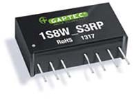
The 1S8W_S3 & 1S8W_D3 Series are specially designed for applications where a wide range input voltage power supplies are isolated from the input power supply in a distributed power supply system on a circuit board. Features:
Download PCB Footprints and Schematic Symbols for free, to download/request, please click the Logo on the right in the below Selection Guide.
| ||||||||||||||||||||||||||||||||||||||||||||||||||||||||||||||||||||||||||||||||||||||||||||||||||||||||||||||||||||||||||||||||||||||||||||||||||||||||||||||||||||||||||||||||||||||||||||||||||||||||||||||||||||||||||||||||||||||||||||||||||||||||||||||||||||||||||||||||||||||||||||||||||||||||||||||||||||||||||||||||||||||||||||||||||||||||||||||||||||||||||||||||||||||||||||||||||||||||||||||||||||||||||||||||||||||||||||||||||||||||||||||||||||||||||||||||||||||||||||||||||||||||||||||||||||||||||||||||||||||||||||||||||||||||||||||||||||||||||||||||||||||||||||||||||
| 1S8W_2RP | SIP8 | 2:1 | 4.5-9; 9-18; 18-36 | 3.3; 5; 9; 12; 15; 24; ±3.3; ±5; ±12; ±15 | 2; 4; 5.2 | • | • | 81% | -40°C - +100°C | 1S8W_2RP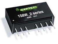
The 1S8W_2 & 1S8W_4 series are specially designed for applications where a wide range input voltage power supplies are isolated from the input power supply in a distributed power supply system on a circuit board. Features:
Download PCB Footprints and Schematic Symbols for free, to download/request, please click the Logo on the right in the below Selection Guide.
| |||||||||||||||||||||||||||||||||||||||||||||||||||||||||||||||||||||||||||||||||||||||||||||||||||||||||||||||||||||||||||||||||||||||||||||||||||||||||||||||||||||||||||||||||||||||||||||||||||||||||||||||||||||||||||||||||||||||||||||||||||||||||||||||||||||||||||||||||||||||||||||||||||||||||||||||||||||||||||||||||||||||||||||||||||||||||||||||||||||||||||||||||||||||||||||||||||||||||||||||||||||||||||||||||||||||||||||||||||||||||||||||||||||||||||||||||||||||||||||||||||||||||||||||||||||||||||||||||||||||||||||||||||||||||||||||||||||||||||||||||||||||||||||||||||
| 1S8W4_2RP | SIP8 | 4:1 | 4.5-18; 9-36; 18-75 | 3.3; 5; 9; 12; 15; 24; ±3.3; ±5; ±12; ±15 | 2 & 4 | • | • | 81% | -40°C - +100°C | 1S8W4_2RP
The 1S8W4_2 & 1S8W4_4 series are specially designed for applications where a wide range input voltage power supplies are isolated from the input power supply in a distributed power supply system on a circuit board. Features:
Download PCB Footprints and Schematic Symbols for free, to download/request, please click the Logo on the right in the below Selection Guide.
|
Series |
Case Size |
Input Range |
Input Voltage (VDC) |
Output Voltage (VDC) |
Output Current (A) |
Isolation (kVDC) |
Regulation |
SCP * |
η max. |
Operating Temp. |
Dimming |
Certs |
||||||||||||||
| 1.5D8A_1U | DIP8 | ±10% | 5 | 5 | 1 | 70% | -40°C - +85°C | 1.5D8A_1U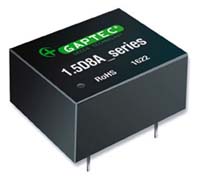
The 1.5D8A_1U cost effective series are specially designed for applications where a single power supply is isolated from the input power supply in a distributed power supply system on a circuit board.
Download PCB Footprints and Schematic Symbols for free, to download/request, please click the Logo on the right in the below Selection Guide.
|
Series |
Case Size |
Input Range |
Input Voltage (VDC) |
Output Voltage (VDC) |
Output Current (A) |
Isolation (kVDC) |
Regulation |
SCP * |
η max. |
Operating Temp. |
Dimming |
Certs |
||||||||||||||||||||||||||||||||||||||||||||||||||||||||||||||||||||||||||||||||||||||||||||||||||||||||||||||||||||||||||||||||||||||||||||||||||||||||||||||||||||||||||||||||||||||||||||||||||||||||||||||||||||||||||||||||||||||||||||||||||||||||||||||||||||||||||||||||||||||||||||||||||||||||||||||||||||||||||||||||||||||||||||||||||||||||||||||||||||||||||||||||||||||||||||||||||||||||||||||||||||||||||||||||||||||||||||||||||||||||||||||||||||||||||||||||||||||||||||||||||||||||
| 2S4E_1U | SIP4 | ±10% | 5; 12; 15; 24; 48 | 3,3; 5; 9; 12; 15; 24 | 1 | 88% | -40°C - +85°C | 2S4E_1U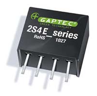
The 2S4E_1U cost effective series are specially designed for applications where a single power supply is isolated from the input power supply in a distributed power supply system on a circuit board.
Download PCB Footprints and Schematic Symbols for free, to download/request, please click the Logo on the right in the below Selection Guide.
| |||||||||||||||||||||||||||||||||||||||||||||||||||||||||||||||||||||||||||||||||||||||||||||||||||||||||||||||||||||||||||||||||||||||||||||||||||||||||||||||||||||||||||||||||||||||||||||||||||||||||||||||||||||||||||||||||||||||||||||||||||||||||||||||||||||||||||||||||||||||||||||||||||||||||||||||||||||||||||||||||||||||||||||||||||||||||||||||||||||||||||||||||||||||||||||||||||||||||||||||||||||||||||||||||||||||||||||||||||||||||||||||||||||||||||||||||||||||||||||||||||||||||||
| 2S4A_1.5UP | SIP4 | ±10% | 5; 24 | 5 | 1.5 | • | 82% | -40°C - +85°C | 2S4A_1.5UP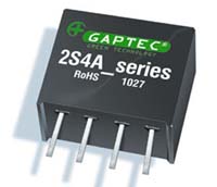
The 2S4A Series are designed for application where isolated output is required from a distributed power system. Features:
Download PCB Footprints and Schematic Symbols for free, to download/request, please click the Logo on the right in the below Selection Guide.
| ||||||||||||||||||||||||||||||||||||||||||||||||||||||||||||||||||||||||||||||||||||||||||||||||||||||||||||||||||||||||||||||||||||||||||||||||||||||||||||||||||||||||||||||||||||||||||||||||||||||||||||||||||||||||||||||||||||||||||||||||||||||||||||||||||||||||||||||||||||||||||||||||||||||||||||||||||||||||||||||||||||||||||||||||||||||||||||||||||||||||||||||||||||||||||||||||||||||||||||||||||||||||||||||||||||||||||||||||||||||||||||||||||||||||||||||||||||||||||||||||||||||||||
| 2S7A_1U | SIP7 | ±10% | 5; 12; 15; 24; 48 | 3.3; 5; 7,2 ; 9; 12; 15; 24; ±3.3; ±5; ±7,2; ±12; ±15; ±18; ±24 | 1 | 82% | -40°C - +85°C | 2S7A_1U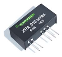
The 2S7A_1U cost effective series are specially designed for applications where a group of polar power supplies are isolated from the input power supply in a distributed power supply system on a circuit board. Features:
Download PCB Footprints and Schematic Symbols for free, to download/request, please click the Logo on the right in the below Selection Guide.
| |||||||||||||||||||||||||||||||||||||||||||||||||||||||||||||||||||||||||||||||||||||||||||||||||||||||||||||||||||||||||||||||||||||||||||||||||||||||||||||||||||||||||||||||||||||||||||||||||||||||||||||||||||||||||||||||||||||||||||||||||||||||||||||||||||||||||||||||||||||||||||||||||||||||||||||||||||||||||||||||||||||||||||||||||||||||||||||||||||||||||||||||||||||||||||||||||||||||||||||||||||||||||||||||||||||||||||||||||||||||||||||||||||||||||||||||||||||||||||||||||||||||||||
| 2S7A_1.5UP | SIP7 | ±10% | 5; 12; 15; 24 | 3.3; 5; 12; 15; 24; ±3.3; ±5; ±12; ±15; ±24 | 1.5 | • | 84% | -40°C - +105°C | UL60950 | 2S7A_1.5UP
The 2S7A_1.5UP Series are specially designed for applications where a group of polar power supplies are isolated from the input power supply in a distributed power supply system on a circuit board. Features:
Download PCB Footprints and Schematic Symbols for free, to download/request, please click the Logo on the right in the below Selection Guide.
| |||||||||||||||||||||||||||||||||||||||||||||||||||||||||||||||||||||||||||||||||||||||||||||||||||||||||||||||||||||||||||||||||||||||||||||||||||||||||||||||||||||||||||||||||||||||||||||||||||||||||||||||||||||||||||||||||||||||||||||||||||||||||||||||||||||||||||||||||||||||||||||||||||||||||||||||||||||||||||||||||||||||||||||||||||||||||||||||||||||||||||||||||||||||||||||||||||||||||||||||||||||||||||||||||||||||||||||||||||||||||||||||||||||||||||||||||||||||||||||||||||||||||
| 2S7A_1RP | SIP7 | ±10% | 5; 12; 15; 24 | 5; 12; 15 | 1 | • | • | 72% | -40°C - +85°C | 2S7A_1RP
The 2S7A_1RP Series are specially designed for applications where a group of polar power supplies are isolated from the input power supply in a distributed power supply system on a circuit board. Features:
Download PCB Footprints and Schematic Symbols for free, to download/request, please click the Logo on the right in the below Selection Guide.
| |||||||||||||||||||||||||||||||||||||||||||||||||||||||||||||||||||||||||||||||||||||||||||||||||||||||||||||||||||||||||||||||||||||||||||||||||||||||||||||||||||||||||||||||||||||||||||||||||||||||||||||||||||||||||||||||||||||||||||||||||||||||||||||||||||||||||||||||||||||||||||||||||||||||||||||||||||||||||||||||||||||||||||||||||||||||||||||||||||||||||||||||||||||||||||||||||||||||||||||||||||||||||||||||||||||||||||||||||||||||||||||||||||||||||||||||||||||||||||||||||||||||||
| 2S7BE_3U | SIP7 | ±10% | 3.3; 5; 12; 24; 48 | 3.3; 5; 9; 12; 15; 24; ±3.3; ±5; ±9; ±12; ±15; ±24 | 3 | -40°C - +85°C | UL60950 | 2S7BE_3U
The 2S7BE_3U series meet reinforced insulation requirements. It is specially designed for applications which require compact size, high isolation, low isolation capacitor and low leakage current power. Features:
Field of application:
Download PCB Footprints and Schematic Symbols for free, to download/request, please click the Logo on the right in the below Selection Guide.
| |||||||||||||||||||||||||||||||||||||||||||||||||||||||||||||||||||||||||||||||||||||||||||||||||||||||||||||||||||||||||||||||||||||||||||||||||||||||||||||||||||||||||||||||||||||||||||||||||||||||||||||||||||||||||||||||||||||||||||||||||||||||||||||||||||||||||||||||||||||||||||||||||||||||||||||||||||||||||||||||||||||||||||||||||||||||||||||||||||||||||||||||||||||||||||||||||||||||||||||||||||||||||||||||||||||||||||||||||||||||||||||||||||||||||||||||||||||||||||||||||||||||||||
| 2S7B_3UP | SIP7 | ±10% | 5; 12; 15; 24 | 5; 12; 15; 24; ±5; ±12; ±15; ±24 | 3 | • | 80% | -40°C - +105°C | UL60950 | 2S7B_3UP
The 2S7B_3UP Series are specially designed for applications where a group of polar power supplies are isolated from the input power supply in a distributed power supply system on a circuit board. Features:
Field of application:
Download PCB Footprints and Schematic Symbols for free, to download/request, please click the Logo on the right in the below Selection Guide.
| |||||||||||||||||||||||||||||||||||||||||||||||||||||||||||||||||||||||||||||||||||||||||||||||||||||||||||||||||||||||||||||||||||||||||||||||||||||||||||||||||||||||||||||||||||||||||||||||||||||||||||||||||||||||||||||||||||||||||||||||||||||||||||||||||||||||||||||||||||||||||||||||||||||||||||||||||||||||||||||||||||||||||||||||||||||||||||||||||||||||||||||||||||||||||||||||||||||||||||||||||||||||||||||||||||||||||||||||||||||||||||||||||||||||||||||||||||||||||||||||||||||||||
| 2S7BE_6U | SIP7 | ±10% | 3.3; 5; 12; 24; 48 | 3.3; 5; 9; 12; 15; 24; ±3.3; ±5; ±9; ±12; ±15; ±24 | 6 | -40°C - +85°C | UL60950 | 2S7BE_6U
The 2S7BE_6U series meet reinforced insulation requirements. It is specially designed for applications which require compact size, high isolation, low isolation capacitor and low leakage current power. Features:
Field of application:
Download PCB Footprints and Schematic Symbols for free, to download/request, please click the Logo on the right in the below Selection Guide.
| |||||||||||||||||||||||||||||||||||||||||||||||||||||||||||||||||||||||||||||||||||||||||||||||||||||||||||||||||||||||||||||||||||||||||||||||||||||||||||||||||||||||||||||||||||||||||||||||||||||||||||||||||||||||||||||||||||||||||||||||||||||||||||||||||||||||||||||||||||||||||||||||||||||||||||||||||||||||||||||||||||||||||||||||||||||||||||||||||||||||||||||||||||||||||||||||||||||||||||||||||||||||||||||||||||||||||||||||||||||||||||||||||||||||||||||||||||||||||||||||||||||||||||
| 2S7B_6UP | SIP7 | ±10% | 5; 12; 24 | 5; 9; 12; 15; ±5; ±9; ±12; ±15 | 6 | • | 80% | -40°C - +95°C | UL60601 | 2S7B_6UP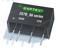
The 2S7B_6UP series meet reinforced insulation requirements. It is specially designed for applications which require compact size, high isolation, low isolation capacitor and low leakage current power. Features:
Field of application:
Download PCB Footprints and Schematic Symbols for free, to download/request, please click the Logo on the right in the below Selection Guide.
| |||||||||||||||||||||||||||||||||||||||||||||||||||||||||||||||||||||||||||||||||||||||||||||||||||||||||||||||||||||||||||||||||||||||||||||||||||||||||||||||||||||||||||||||||||||||||||||||||||||||||||||||||||||||||||||||||||||||||||||||||||||||||||||||||||||||||||||||||||||||||||||||||||||||||||||||||||||||||||||||||||||||||||||||||||||||||||||||||||||||||||||||||||||||||||||||||||||||||||||||||||||||||||||||||||||||||||||||||||||||||||||||||||||||||||||||||||||||||||||||||||||||||
| 2S7W_1RP | SIP7 | 2:1 | 4.5-9; 9-18; 18-36; 36-72 | 3.3; 5; 9; 12; 15; ±3,3; ±5; ±9; ±12; ±15 | 1 | • | • | 84% | -40°C - +100°C | 2S7W_1RP
The 2S7W_1RP Series are specially designed for applications where a group of polar power supplies are isolated from the input power supply in a distributed power supply system on a circuit board. Features:
Download PCB Footprints and Schematic Symbols for free, to download/request, please click the Logo on the right in the below Selection Guide.
| |||||||||||||||||||||||||||||||||||||||||||||||||||||||||||||||||||||||||||||||||||||||||||||||||||||||||||||||||||||||||||||||||||||||||||||||||||||||||||||||||||||||||||||||||||||||||||||||||||||||||||||||||||||||||||||||||||||||||||||||||||||||||||||||||||||||||||||||||||||||||||||||||||||||||||||||||||||||||||||||||||||||||||||||||||||||||||||||||||||||||||||||||||||||||||||||||||||||||||||||||||||||||||||||||||||||||||||||||||||||||||||||||||||||||||||||||||||||||||||||||||||||||
| 2S7WA_3RP | SIP7 | 2:1 | 4.5-9; 9-18; 18-36 | 5; 9; 12; 15; 24 | 3 | • | • | 83% | -40°C - +95°C | 2S7WA_3RP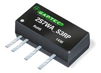
The 2S7WA Series are specially designed for applications where a group of polar power supplies are isolated from the input power supply in a distributed power supply system on a circuit board. Features:
Download PCB Footprints and Schematic Symbols for free, to download/request, please click the Logo on the right in the below Selection Guide.
| |||||||||||||||||||||||||||||||||||||||||||||||||||||||||||||||||||||||||||||||||||||||||||||||||||||||||||||||||||||||||||||||||||||||||||||||||||||||||||||||||||||||||||||||||||||||||||||||||||||||||||||||||||||||||||||||||||||||||||||||||||||||||||||||||||||||||||||||||||||||||||||||||||||||||||||||||||||||||||||||||||||||||||||||||||||||||||||||||||||||||||||||||||||||||||||||||||||||||||||||||||||||||||||||||||||||||||||||||||||||||||||||||||||||||||||||||||||||||||||||||||||||||
| 2S7WB_3RP | SIP7 | 2:1 | 4.5-9; 9-18; 18-36 | 5; 9; 12; 15; 24 | 3 | • | • | 83% | -40°C - +95°C | 2S7WB_3RP
The 2S7WB Series are specially designed for applications where a group of polar power supplies are isolated from the input power supply in a distributed power supply system on a circuit board. Features:
Download PCB Footprints and Schematic Symbols for free, to download/request, please click the Logo on the right in the below Selection Guide.
| |||||||||||||||||||||||||||||||||||||||||||||||||||||||||||||||||||||||||||||||||||||||||||||||||||||||||||||||||||||||||||||||||||||||||||||||||||||||||||||||||||||||||||||||||||||||||||||||||||||||||||||||||||||||||||||||||||||||||||||||||||||||||||||||||||||||||||||||||||||||||||||||||||||||||||||||||||||||||||||||||||||||||||||||||||||||||||||||||||||||||||||||||||||||||||||||||||||||||||||||||||||||||||||||||||||||||||||||||||||||||||||||||||||||||||||||||||||||||||||||||||||||||
| 2D14B_1U | DIP14 | ±10% | 3.3; 5; 12; 24; 48 | 3.3; 5; 7,2; 9; 12; 15; 18; 24; ±3,3; ±5; ±7,2; ±9; ±12; ±15; ±18; ±24 | 1 | 82% | -40°C - +85°C | 2D14B_1U
The 2D14B_1U Series are specially designed for cost effective applications. Features:
Download PCB Footprints and Schematic Symbols for free, to download/request, please click the Logo on the right in the below Selection Guide.
| |||||||||||||||||||||||||||||||||||||||||||||||||||||||||||||||||||||||||||||||||||||||||||||||||||||||||||||||||||||||||||||||||||||||||||||||||||||||||||||||||||||||||||||||||||||||||||||||||||||||||||||||||||||||||||||||||||||||||||||||||||||||||||||||||||||||||||||||||||||||||||||||||||||||||||||||||||||||||||||||||||||||||||||||||||||||||||||||||||||||||||||||||||||||||||||||||||||||||||||||||||||||||||||||||||||||||||||||||||||||||||||||||||||||||||||||||||||||||||||||||||||||||||
| 2D14B_1.5UP | DIP14 | ±10% | 3.3; 5; 9; 12; 15; 24 | 3.3; 5; 9; 12; 15; 24; ±5; ±9; ±12; ±15; ±24 | 1.5 | • | 85% | -40°C - +95°C | UL60950 | 2D14B_1.5UP
The 2D14B_1.5UP Series are specially designed for applications where a group of polar power supplies are isolated from the input power supply in a distributed power supply system on a circuit board. Features:
Field of application:
Download PCB Footprints and Schematic Symbols for free, to download/request, please click the Logo on the right in the below Selection Guide.
| |||||||||||||||||||||||||||||||||||||||||||||||||||||||||||||||||||||||||||||||||||||||||||||||||||||||||||||||||||||||||||||||||||||||||||||||||||||||||||||||||||||||||||||||||||||||||||||||||||||||||||||||||||||||||||||||||||||||||||||||||||||||||||||||||||||||||||||||||||||||||||||||||||||||||||||||||||||||||||||||||||||||||||||||||||||||||||||||||||||||||||||||||||||||||||||||||||||||||||||||||||||||||||||||||||||||||||||||||||||||||||||||||||||||||||||||||||||||||||||||||||||||||
| 2D14C_3UP | DIP14 | ±10% | 5; 12; 15 | 5; 9; 12; 15; 24; ±5; ±9; ±12; ±15; ±24 | 3 | • | 85% | -40°C - +95°C | UL60950 | 2D14C_3UP
The 2D14C_3UP Series are specially designed for applications where a group of polar power supplies are isolated from the input power supply in a distributed power supply system on a circuit board. Features:
Field of application:
Download PCB Footprints and Schematic Symbols for free, to download/request, please click the Logo on the right in the below Selection Guide.
| |||||||||||||||||||||||||||||||||||||||||||||||||||||||||||||||||||||||||||||||||||||||||||||||||||||||||||||||||||||||||||||||||||||||||||||||||||||||||||||||||||||||||||||||||||||||||||||||||||||||||||||||||||||||||||||||||||||||||||||||||||||||||||||||||||||||||||||||||||||||||||||||||||||||||||||||||||||||||||||||||||||||||||||||||||||||||||||||||||||||||||||||||||||||||||||||||||||||||||||||||||||||||||||||||||||||||||||||||||||||||||||||||||||||||||||||||||||||||||||||||||||||||
| 2S8W_1RP | SIP8 | 2:1 | 4.5-9; 9-18; 18-36; 36-72 | 3.3; 5; 9; 12; 15; 24; ±3.3; ±5; ±9; ±12; ±15; ±24 | 1 & 3 | • | • | 80% | -40°C - +85°C | UL60950 | 2S8W_1RP
The 2S8W_1RP & 2S8W_3RP series are specially designed for applications where a wide range input voltage power supplies are isolated from the input power supply in a distributed power supply system on a circuit board. Features:
Download PCB Footprints and Schematic Symbols for free, to download/request, please click the Logo on the right in the below Selection Guide.
| ||||||||||||||||||||||||||||||||||||||||||||||||||||||||||||||||||||||||||||||||||||||||||||||||||||||||||||||||||||||||||||||||||||||||||||||||||||||||||||||||||||||||||||||||||||||||||||||||||||||||||||||||||||||||||||||||||||||||||||||||||||||||||||||||||||||||||||||||||||||||||||||||||||||||||||||||||||||||||||||||||||||||||||||||||||||||||||||||||||||||||||||||||||||||||||||||||||||||||||||||||||||||||||||||||||||||||||||||||||||||||||||||||||||||||||||||||||||||||||||||||||||||
| 2S8W_2RP | SIP8 | 2:1 | 4.5-9; 9-18; 18-36; 36-75 | 3.3; 5; 9; 12; 15; ±3.3; ±5; ±12; ±15 | 2 & 4 | • | • | 85% | -40°C - +100°C | 2S8W_2RP
The 2S8W_2RP & 2S8W_4RP series are specially designed for applications where a wide range input voltage power supplies are isolated from the input power supply in a distributed power supply system on a circuit board. Features:
Download PCB Footprints and Schematic Symbols for free, to download/request, please click the Logo on the right in the below Selection Guide.
| |||||||||||||||||||||||||||||||||||||||||||||||||||||||||||||||||||||||||||||||||||||||||||||||||||||||||||||||||||||||||||||||||||||||||||||||||||||||||||||||||||||||||||||||||||||||||||||||||||||||||||||||||||||||||||||||||||||||||||||||||||||||||||||||||||||||||||||||||||||||||||||||||||||||||||||||||||||||||||||||||||||||||||||||||||||||||||||||||||||||||||||||||||||||||||||||||||||||||||||||||||||||||||||||||||||||||||||||||||||||||||||||||||||||||||||||||||||||||||||||||||||||||
| 2S9W4_1.5RP | SIP9 | 4:1 | 9-36; 18-75 | 3.3; 5; 9; 12; 15; ±5; ±9; ±12; ±15 | 1.5 | • | • | 79% | -40°C - +85°C | 2S9W4_1.5RP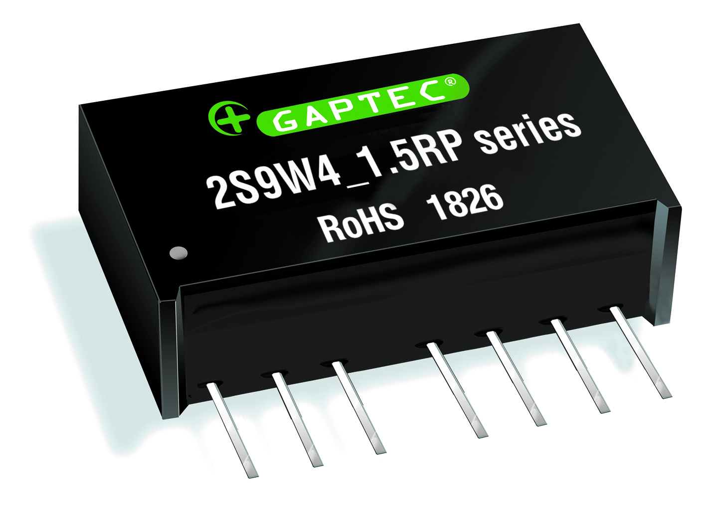
The 2S9W4_1.5 series are specially designed for applications where a wide range input voltage power supplies are isolated from the input power supply in a distributed power supply system on a circuit board. Features:
Download PCB Footprints and Schematic Symbols for free, to download/request, please click the Logo on the right in the below Selection Guide.
| |||||||||||||||||||||||||||||||||||||||||||||||||||||||||||||||||||||||||||||||||||||||||||||||||||||||||||||||||||||||||||||||||||||||||||||||||||||||||||||||||||||||||||||||||||||||||||||||||||||||||||||||||||||||||||||||||||||||||||||||||||||||||||||||||||||||||||||||||||||||||||||||||||||||||||||||||||||||||||||||||||||||||||||||||||||||||||||||||||||||||||||||||||||||||||||||||||||||||||||||||||||||||||||||||||||||||||||||||||||||||||||||||||||||||||||||||||||||||||||||||||||||||
| 2D16WA_1.5RP | DIP16 | 2:1 | 4,5-9; 9-18; 18-36 | 3.3; 5; 12; 15; 24; ±5; ±12; ±15 | 1.5 | • | • | 80% | -40°C - +85°C | 2D16WA_1.5RP
The 2D16W_1.5RP are specially designed for applications where a wide range input voltage power supplies are isolated from the input power supply in a distributed power supply system on a circuit board. Features:
Download PCB Footprints and Schematic Symbols for free, to download/request, please click the Logo on the right in the below Selection Guide.
|
Series |
Case Size |
Input Range |
Input Voltage (VDC) |
Output Voltage (VDC) |
Output Current (A) |
Isolation (kVDC) |
Regulation |
SCP * |
η max. |
Operating Temp. |
Dimming |
Certs |
||||||||||||||||||||||||||||||||||||||||||||||||||||||||||||||||||||||||||||||||||||||||||||||||||||||||||||||||||||||||||||||||||||||||||||||||||||||||||||||||||||||||||||||||||||||||||||||||||||||||||||||||||||||||||||||||||||||||||||||||||||||||||||||||||||||||||||||||
| 3S4A_1U | SIP4 | ±10% | 5; 12 | 5; 9; 12; 15 | 1 | 86% | -40°C - +85°C | 3S4A_1U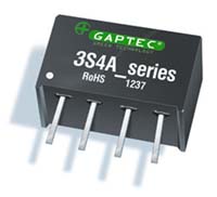
The 3S4A_1U series are miniature, isolated 3W DC/DC converters in a SIP package. They offer the ideal solution in many space critical applications for board level power distribution. The internal SMD construction makes it possible to offer a product with high performance at low cost. The series offers smaller size, improved efficiency, lower output ripple noise.
Download PCB Footprints and Schematic Symbols for free, to download/request, please click the Logo on the right in the below Selection Guide.
| |||||||||||||||||||||||||||||||||||||||||||||||||||||||||||||||||||||||||||||||||||||||||||||||||||||||||||||||||||||||||||||||||||||||||||||||||||||||||||||||||||||||||||||||||||||||||||||||||||||||||||||||||||||||||||||||||||||||||||||||||||||||||||||||||||||||||||||||||||
| 3S4A_1UP | SIP4 | ±10% | 5; 12 | 5; 9; 12; 15; 18 | 1 | • | 86% | -40°C - +85°C | 3S4A_1UP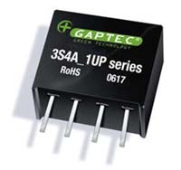
The 3S4A_1UP series are miniature, isolated 3W DC/DC converters in a SIP package. They offer the ideal solution in many space critical applications for board level power distribution. The internal SMD construction makes it possible to offer a product with high performance at low cost. The series offers smaller size, improved efficiency, lower output ripple noise.
Download PCB Footprints and Schematic Symbols for free, to download/request, please click the Logo on the right in the below Selection Guide.
| ||||||||||||||||||||||||||||||||||||||||||||||||||||||||||||||||||||||||||||||||||||||||||||||||||||||||||||||||||||||||||||||||||||||||||||||||||||||||||||||||||||||||||||||||||||||||||||||||||||||||||||||||||||||||||||||||||||||||||||||||||||||||||||||||||||||||||||||||||
| 3S7A_1U | SIP7 | ±10% | 5; 12 | 5; 9; 12; 15; ±5; ±9; ±12; ±15 | 1 | 90% | -40°C - +85°C | 3S7A_1U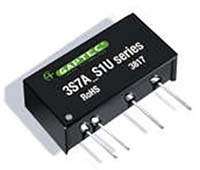
The 3S7A_1U Series is specially designed for applications where a single power supply is highly isolated from the input power supply in a distributed power supply system on a circuit board.
Download PCB Footprints and Schematic Symbols for free, to download/request, please click the Logo on the right in the below Selection Guide.
| |||||||||||||||||||||||||||||||||||||||||||||||||||||||||||||||||||||||||||||||||||||||||||||||||||||||||||||||||||||||||||||||||||||||||||||||||||||||||||||||||||||||||||||||||||||||||||||||||||||||||||||||||||||||||||||||||||||||||||||||||||||||||||||||||||||||||||||||||||
| 3S7A_1.5UP | SIP7 | ±10% | 3.3; 5; 12; 24; 48 | 3.3; 5; 9; 12; 15; 24 | 1.5 | • | 88% | -40°C - +105°C | 3S7A_1.5UP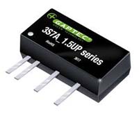
The 3S7A_1.5UP Series is specially designed for applications where a single power supply is highly isolated from the input power supply in a distributed power supply system on a circuit board.
Download PCB Footprints and Schematic Symbols for free, to download/request, please click the Logo on the right in the below Selection Guide.
| ||||||||||||||||||||||||||||||||||||||||||||||||||||||||||||||||||||||||||||||||||||||||||||||||||||||||||||||||||||||||||||||||||||||||||||||||||||||||||||||||||||||||||||||||||||||||||||||||||||||||||||||||||||||||||||||||||||||||||||||||||||||||||||||||||||||||||||||||||
| 3S6W4_1.6RP | SIP6 | 4:1 | 4.5-18; 9-36; 18-75 | 3.3; 5; 12; 15; ±5; ±12; ±15 | 1.6 | • | • | 84% | -40°C - +71°C | 3S6W4_1.6RP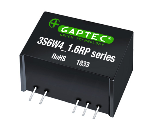
The 3S6W4_1.6RP series are specially designed for applications where a wide range input voltage power supplies are isolated from the input power supply in a distributed power supply system on a circuit board. Features:
Download PCB Footprints and Schematic Symbols for free, to download/request, please click the Logo on the right in the below Selection Guide.
| |||||||||||||||||||||||||||||||||||||||||||||||||||||||||||||||||||||||||||||||||||||||||||||||||||||||||||||||||||||||||||||||||||||||||||||||||||||||||||||||||||||||||||||||||||||||||||||||||||||||||||||||||||||||||||||||||||||||||||||||||||||||||||||||||||||||||||||||||
| 3S7B_3U | SIP7 | ±10% | 5; 12 | 5; 9; 12; 15; ±5; ±9; ±12; ±15 | 3 | 90% | -40°C - +85°C | 3S7B_3U
The 3S7B_3U Series is specially designed for applications where a single power supply is highly isolated from the input power supply in a distributed power supply system on a circuit board.
Download PCB Footprints and Schematic Symbols for free, to download/request, please click the Logo on the right in the below Selection Guide.
| |||||||||||||||||||||||||||||||||||||||||||||||||||||||||||||||||||||||||||||||||||||||||||||||||||||||||||||||||||||||||||||||||||||||||||||||||||||||||||||||||||||||||||||||||||||||||||||||||||||||||||||||||||||||||||||||||||||||||||||||||||||||||||||||||||||||||||||||||||
| 3S7B_3UP | SIP7 | ±10% | 3.3; 5; 12; 24 | 3.3; 5; 9; 12; 15; ±5; ±9; ±12; ±15; ±24 | 3 | • | 87% | -40°C - +85°C | 3S7B_3UP
The 3S7B_3UP Series is specially designed for applications where a single power supply is highly isolated from the input power supply in a distributed power supply system on a circuit board.
Download PCB Footprints and Schematic Symbols for free, to download/request, please click the Logo on the right in the below Selection Guide.
| ||||||||||||||||||||||||||||||||||||||||||||||||||||||||||||||||||||||||||||||||||||||||||||||||||||||||||||||||||||||||||||||||||||||||||||||||||||||||||||||||||||||||||||||||||||||||||||||||||||||||||||||||||||||||||||||||||||||||||||||||||||||||||||||||||||||||||||||||||
| 3S8A_T1.5U | SIP8 | ±10% | 4; 5; 12 | -24; -48; -72 | 1.5 | • | 85% | -40°C - +105°C | 3S8A_T1.5U
The 3S8A_1.5U Series offers smaller size, improved efficiency, lower output ripple noise and 1.5KVDC isolation and providing three output voltages of -24V, -48V and -72V from a single isolated 4V, 5V and 12V input voltage.
Download PCB Footprints and Schematic Symbols for free, to download/request, please click the Logo on the right in the below Selection Guide.
| ||||||||||||||||||||||||||||||||||||||||||||||||||||||||||||||||||||||||||||||||||||||||||||||||||||||||||||||||||||||||||||||||||||||||||||||||||||||||||||||||||||||||||||||||||||||||||||||||||||||||||||||||||||||||||||||||||||||||||||||||||||||||||||||||||||||||||||||||||
| 3S8W_1.5RP | SIP8 | 2:1 | 4.5-9; 9-18; 18-36; 36-75 | 5; 9; 12; 15; ±5; ±9; ±12; ±15 | 1.5 | • | • | 84% | -40°C - +85°C | 3S8W_1.5RP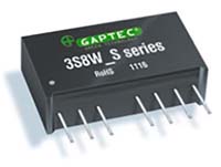
The 3S8W_S & 3S8W_D Series are specially designed for applications where a wide range input voltage power supplies are isolated from the input power supply in a distributed power supply system on a circuit board. For these DC-DC converters, You can reduce the design point of failure and save the development of micro power supply‘s manpower, material and time costs, also better ensure product quality stability, protect safety and reliability of the end of products. Features:
Download PCB Footprints and Schematic Symbols for free, to download/request, please click the Logo on the right in the below Selection Guide.
| |||||||||||||||||||||||||||||||||||||||||||||||||||||||||||||||||||||||||||||||||||||||||||||||||||||||||||||||||||||||||||||||||||||||||||||||||||||||||||||||||||||||||||||||||||||||||||||||||||||||||||||||||||||||||||||||||||||||||||||||||||||||||||||||||||||||||||||||||
| 3S8EW_1.5RP | SIP8 | 2:1 | 9-18; 18-36; 36-72 | 3.3; 5; 9; 12; 15; 24 | 1.5 | • | • | 80% | -40°C - +85°C | 3S8EW_1.5RP
The 3S8EW_1.5RP cost effective series are specially designed for applications where a wide range input voltage power supplies are isolated from the input power supply in a distributed power supply system on a circuit board. Features:
Download PCB Footprints and Schematic Symbols for free, to download/request, please click the Logo on the right in the below Selection Guide.
| |||||||||||||||||||||||||||||||||||||||||||||||||||||||||||||||||||||||||||||||||||||||||||||||||||||||||||||||||||||||||||||||||||||||||||||||||||||||||||||||||||||||||||||||||||||||||||||||||||||||||||||||||||||||||||||||||||||||||||||||||||||||||||||||||||||||||||||||||
| 3D8W_1.5RP | DIP | 2:1 | 9-18; 18-36 | 3.3; 5; 12; 15; 24 | 1.5 | • | • | 80% | -40°C - +85°C | UL62368 | 3D8W_1.5RP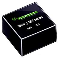
The 3D8W_1.5RP Series is specially designed for applications where a wide range input voltage power supplies are isolated from the input power supply in a distributed power supply system on a circuit board. Features:
Field of application:
Download PCB Footprints and Schematic Symbols for free, to download/request, please click the Logo on the right in the below Selection Guide.
| ||||||||||||||||||||||||||||||||||||||||||||||||||||||||||||||||||||||||||||||||||||||||||||||||||||||||||||||||||||||||||||||||||||||||||||||||||||||||||||||||||||||||||||||||||||||||||||||||||||||||||||||||||||||||||||||||||||||||||||||||||||||||||||||||||||||||||||||||
| 3D8W4_1.6RP | DIP | 4:1 | 4,5-18; 9-36; 18-75 | 3,3; 5; 12; 15; ±5; ±12; ±15 | 1.6 | 84% | -40°C - +80°C | 3D8W4_1.6RP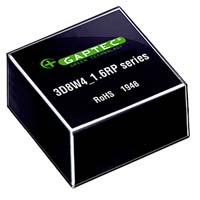
The 3D8W4_1.6RP Series is specially designed for applications where a wide range input voltage power supplies are isolated from the input power supply in a distributed power supply system on a circuit board. Features:
Field of application:
Download PCB Footprints and Schematic Symbols for free, to download/request, please click the Logo on the right in the below Selection Guide.
| |||||||||||||||||||||||||||||||||||||||||||||||||||||||||||||||||||||||||||||||||||||||||||||||||||||||||||||||||||||||||||||||||||||||||||||||||||||||||||||||||||||||||||||||||||||||||||||||||||||||||||||||||||||||||||||||||||||||||||||||||||||||||||||||||||||||||||||||||||
| 3S8W_1.6RP | SIP8 | 2:1 | 4.5-9; 9-18; 18-36; 36-75 | 3,3; 5; 12; 15; ±5; ±12; ±15 | 1.6 | • | • | 84% | -40°C - +85°C | UL60950 | 3S8W_1.6RP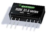
The 3S8W_1.6RP Series are specially designed for cost effective applications where a wide range input voltage power supplies are isolated from the input power supply in a distributed power supply system on a circuit board. Features:
Download PCB Footprints and Schematic Symbols for free, to download/request, please click the Logo on the right in the below Selection Guide.
| ||||||||||||||||||||||||||||||||||||||||||||||||||||||||||||||||||||||||||||||||||||||||||||||||||||||||||||||||||||||||||||||||||||||||||||||||||||||||||||||||||||||||||||||||||||||||||||||||||||||||||||||||||||||||||||||||||||||||||||||||||||||||||||||||||||||||||||||||
| 3S8W_3RP | SIP8 | 2:1 | 4.5-9; 9-18; 18-36; 36-75 | 3.3; 5; 9; 12; 15; ±5; ±9; ±12; ±15 | 3 | • | • | 83% | -40°C - +85°C | 3S8W_3RP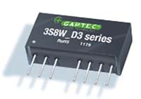
The 3S8W_S3 & 3S8W_D3 Series are specially designed for applications where a wide range input voltage power supplies are isolated from the input power supply in a distributed power supply system on a circuit board. For these DC-DC converters, You can reduce the design point of failure and save the development of micro power supply‘s manpower, material and time costs, also better ensure product quality stability, protect safety and reliability of the end of products. Features:
Download PCB Footprints and Schematic Symbols for free, to download/request, please click the Logo on the right in the below Selection Guide.
| |||||||||||||||||||||||||||||||||||||||||||||||||||||||||||||||||||||||||||||||||||||||||||||||||||||||||||||||||||||||||||||||||||||||||||||||||||||||||||||||||||||||||||||||||||||||||||||||||||||||||||||||||||||||||||||||||||||||||||||||||||||||||||||||||||||||||||||||||
| 3S8W_2RP | SIP8 | 2:1 | 4.5-9; 9-18; 18-36; 36-75 | 3.3; 5; 9; 12; 15; ±5; ±12; ±15 | 2 & 4 | • | • | 86% | -40°C - +100°C | 3S8W_2RP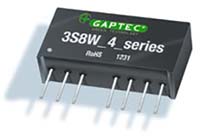
The 3S8W_2RP & 3S8W_4RP series are specially designed for applications where a wide range input voltage power supplies are isolated from the input power supply in a distributed power supply system on a circuit board. Features:
Download PCB Footprints and Schematic Symbols for free, to download/request, please click the Logo on the right in the below Selection Guide.
| |||||||||||||||||||||||||||||||||||||||||||||||||||||||||||||||||||||||||||||||||||||||||||||||||||||||||||||||||||||||||||||||||||||||||||||||||||||||||||||||||||||||||||||||||||||||||||||||||||||||||||||||||||||||||||||||||||||||||||||||||||||||||||||||||||||||||||||||||
| 3S8W4_2RP | SIP8 | 4:1 | 4.5-18; 9-36; 18-75 | 3.3; 5; 12; 15; ±3.3; ±5; ±12; ±15 | 2 & 4 | • | • | 86% | -40°C - +100°C | 3S8W4_2RP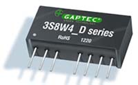
The 3S8W4_2RP & 3S8W4_4RP series are specially designed for applications where a wide range input voltage power supplies are isolated from the input power supply in a distributed power supply system on a circuit board. Features:
Download PCB Footprints and Schematic Symbols for free, to download/request, please click the Logo on the right in the below Selection Guide.
| |||||||||||||||||||||||||||||||||||||||||||||||||||||||||||||||||||||||||||||||||||||||||||||||||||||||||||||||||||||||||||||||||||||||||||||||||||||||||||||||||||||||||||||||||||||||||||||||||||||||||||||||||||||||||||||||||||||||||||||||||||||||||||||||||||||||||||||||||
| 3S8W_4.3RP | SIP8 | 2:1 | 7-18 | 15 | 4.3 | • | • | 83% | -40°C - +105°C | 3S8W_4.3RP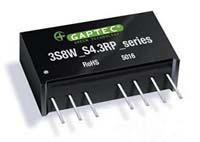
The 3S8W_4.3RP series are isolated 3W DC-DC products with 2:1 input voltage. They feature a production process in accordance with TS16949 system control, the components meet AEC-Q100 standard Features: SIP8 Package (L x W x H) 22.0 x 9.5 x 12.0 mm 3W Single Output Ultra Wide 2:1 Input Voltage Range Meet AEC-Q100 standard / TS-16949 High Efficiency up to 82% I/O Isolation 4.3KVDC Version Operating Temperature Range: -40°C to +105°C Continuous Short Circuit Protection (SCP) Remote ON/OFF Control Internal PI-Filtering
Download PCB Footprints and Schematic Symbols for free, to download/request, please click the Logo on the right in the below Selection Guide.
| |||||||||||||||||||||||||||||||||||||||||||||||||||||||||||||||||||||||||||||||||||||||||||||||||||||||||||||||||||||||||||||||||||||||||||||||||||||||||||||||||||||||||||||||||||||||||||||||||||||||||||||||||||||||||||||||||||||||||||||||||||||||||||||||||||||||||||||||||
| 3DAW_1.5 | DIP24 | 2:1 | 4.5-9; 9-18; 18-36; 36-72 | 5; 9; 12; 15; 24; ±9; ±12; ±15; ±24 | 1.5 | • | • | 81% | -40°C - +85°C | UL60950 | 3DAW_1.5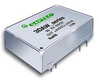
The 3DAW series are specially designed for applications where a wide range input voltage power supplies are isolated from the input power supply in a distributed power supply system on a circuit board. Features:
Download PCB Footprints and Schematic Symbols for free, to download/request, please click the Logo on the right in the below Selection Guide.
| ||||||||||||||||||||||||||||||||||||||||||||||||||||||||||||||||||||||||||||||||||||||||||||||||||||||||||||||||||||||||||||||||||||||||||||||||||||||||||||||||||||||||||||||||||||||||||||||||||||||||||||||||||||||||||||||||||||||||||||||||||||||||||||||||||||||||||||||||
| 3DAW_3 | DIP24 | 2:1 | 4.5-9; 9-18; 18-36; 36-75 | 3.3; 5; 12; 15; 24; ±9; ±12; ±15 | 3 | • | • | 86% | -40°C - +85°C | UL60950 | 3DAW_3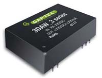
The 3DAW_3 series are specially designed for applications where a wide range input voltage power supplies are isolated from the input power supply in a distributed power supply system on a circuit board. Features:
Download PCB Footprints and Schematic Symbols for free, to download/request, please click the Logo on the right in the below Selection Guide.
| ||||||||||||||||||||||||||||||||||||||||||||||||||||||||||||||||||||||||||||||||||||||||||||||||||||||||||||||||||||||||||||||||||||||||||||||||||||||||||||||||||||||||||||||||||||||||||||||||||||||||||||||||||||||||||||||||||||||||||||||||||||||||||||||||||||||||||||||||
| 3DAW_2 | DIP24 | 2:1 | 4.5-9; 9-18; 18-36; 36-75 | 3.3; 5; 12; 15; ±3.3; ±5; ±12; ±15 | 2; 4; 6 | • | • | 85% | -40°C - +100°C | 3DAW_2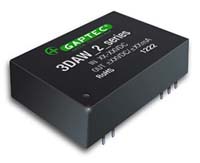
The 3DAW series are specially designed for applications where a wide range input voltage power supplies are isolated from the input power supply in a distributed power supply system on a circuit board. Features:
Download PCB Footprints and Schematic Symbols for free, to download/request, please click the Logo on the right in the below Selection Guide.
| |||||||||||||||||||||||||||||||||||||||||||||||||||||||||||||||||||||||||||||||||||||||||||||||||||||||||||||||||||||||||||||||||||||||||||||||||||||||||||||||||||||||||||||||||||||||||||||||||||||||||||||||||||||||||||||||||||||||||||||||||||||||||||||||||||||||||||||||||
| 3DAW4_1.5 | DIP24 | 4:1 | 9-36; 18-72 | 3.3; 5; 9; 12; 15; 24 | 1.5 | • | • | 83% | -40°C - +85°C | 3DAW4_1.5
The 3DAW4_1.5 series are specially designed for applications where a wide range input voltage power supplies are isolated from the input power supply in a distributed power supply system on a circuit board. Features:
Download PCB Footprints and Schematic Symbols for free, to download/request, please click the Logo on the right in the below Selection Guide.
| |||||||||||||||||||||||||||||||||||||||||||||||||||||||||||||||||||||||||||||||||||||||||||||||||||||||||||||||||||||||||||||||||||||||||||||||||||||||||||||||||||||||||||||||||||||||||||||||||||||||||||||||||||||||||||||||||||||||||||||||||||||||||||||||||||||||||||||||||
| 3DAW4_2 | DIP24 | 4:1 | 4.5-18; 9-36; 18-75 | 3.3; 5; 12; 15; ±5; ±12; ±15 | 2; 4; 6 | • | • | 86% | -40°C - +100°C | 3DAW4_2
The 3DAW4 series are specially designed for applications where a wide range input voltage power supplies are isolated from the input power supply in a distributed power supply system on a circuit board. Features:
Download PCB Footprints and Schematic Symbols for free, to download/request, please click the Logo on the right in the below Selection Guide.
|
Series |
Case Size |
Input Range |
Input Voltage (VDC) |
Output Voltage (VDC) |
Output Current (A) |
Isolation (kVDC) |
Regulation |
SCP * |
η max. |
Operating Temp. |
Dimming |
Certs |
||||||||||||||||||||||||||||||||||||||||||||||||||||||||||||||||||||||||||||||||||||||||||||||||||||||||||||||||||||||||||||||||||||||||||||||||||||||||||||||||||||||||||||||||||||||||||||||||||||||||||||||||||||||||||||||||
| 5S8W_2RP | SIP8 | 2:1 | 4.5-9; 9-18; 18-36; 36-75 | 3.3; 5; 12; 15; ±5; ±12; ±15 | 2; 4 | • | • | 85% | -40°C - +100°C | 5S8W_2RP
The 5S8W_2RP & 5S8W_4RP series are specially designed for applications where a wide range input voltage power supplies are isolated from the input power supply in a distributed power supply system on a circuit board. Features:
Download PCB Footprints and Schematic Symbols for free, to download/request, please click the Logo on the right in the below Selection Guide.
| |||||||||||||||||||||||||||||||||||||||||||||||||||||||||||||||||||||||||||||||||||||||||||||||||||||||||||||||||||||||||||||||||||||||||||||||||||||||||||||||||||||||||||||||||||||||||||||||||||||||||||||||||||||||||||||||||
| 5S8W4_2RP | SIP8 | 4:1 | 9-36; 18-75 | 3.3; 5; 12; 15; ±5; ±12; ±15 | 2; 4 | • | • | 85% | -40°C - +85°C | 5S8W4_2RP
The 5S8W4_2RP & 5S8W4_4RP series are specially designed for applications where a wide range input voltage power supplies are isolated from the input power supply in a distributed power supply system on a circuit board. Features:
Download PCB Footprints and Schematic Symbols for free, to download/request, please click the Logo on the right in the below Selection Guide.
| |||||||||||||||||||||||||||||||||||||||||||||||||||||||||||||||||||||||||||||||||||||||||||||||||||||||||||||||||||||||||||||||||||||||||||||||||||||||||||||||||||||||||||||||||||||||||||||||||||||||||||||||||||||||||||||||||
| 5DAW_2 | DIP24 | 2:1 | 4.5-9; 9-18; 18-36; 36-75 | 3.3; 5; 12; 15; ±5; ±12; ±15 | 2; 4; 6 | • | • | 87% | -40°C - +100°C | 5DAW_2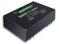
The 5DAW_2 series are specially designed for applications where a wide range input voltage power supplies are isolated from the input power supply in a distributed power supply system on a circuit board. Features:
Download PCB Footprints and Schematic Symbols for free, to download/request, please click the Logo on the right in the below Selection Guide.
| |||||||||||||||||||||||||||||||||||||||||||||||||||||||||||||||||||||||||||||||||||||||||||||||||||||||||||||||||||||||||||||||||||||||||||||||||||||||||||||||||||||||||||||||||||||||||||||||||||||||||||||||||||||||||||||||||
| 5DAW4_2 | DIP24 | 4:1 | 9-36; 18-75 | 3.3; 5; 9; 12; 15; ±5; ±9; ±12; ±15 | 2; 4; 6 | • | • | 85% | -40°C - +100°C | 5DAW4_2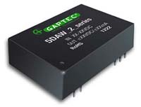
The 5DAW_2 series are specially designed for applications where a wide range input voltage power supplies are isolated from the input power supply in a distributed power supply system on a circuit board. Features:
Download PCB Footprints and Schematic Symbols for free, to download/request, please click the Logo on the right in the below Selection Guide.
|
Series |
Case Size |
Input Range |
Input Voltage (VDC) |
Output Voltage (VDC) |
Output Current (A) |
Isolation (kVDC) |
Regulation |
SCP * |
η max. |
Operating Temp. |
Dimming |
Certs |
||||||||||||||||||||||||||||||||||||||||||||||||||||||||||||||||||||||||||||||||||||||||||||||||||||||||||||||||||||||||||||||||||||||||||||||||||||||||||||||||||||||||||||||||||||||||||||||||||||||||
| 6S8W_1.6RP | SIP8 | 2:1 | 9-18; 18-36 | 3.3; 5; 9; 12; 15; 24 | 1.6 | • | • | 87% | -40°C - +85°C | 6S8W_1.6RP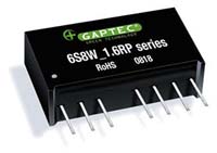
The 6S8W_1.6 Series is an excellent performance and high power density design. The highest efficiency allows high operating temperatures up to 105°C. Features:
Download PCB Footprints and Schematic Symbols for free, to download/request, please click the Logo on the right in the below Selection Guide.
| |||||||||||||||||||||||||||||||||||||||||||||||||||||||||||||||||||||||||||||||||||||||||||||||||||||||||||||||||||||||||||||||||||||||||||||||||||||||||||||||||||||||||||||||||||||||||||||||||||||||||
| 6S8W_3RP | SIP8 | 2:1 | 4.5-9; 9-18; 18-36; 36-75 | 5; 9; 12; 15; ±5; ±12; ±15 | 3 | • | • | 88% | -40°C - +85°C | 6S8W_3RP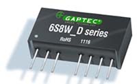
The 6S8W_3 series is an excellent performance and high power density design. The highest efficiency allows high operating temperatures.The very low stand-by (no-load) input power consumption 50mW typ,makes them an ideal solution for application in battery-powered equipment and instrumentation. Features:
Download PCB Footprints and Schematic Symbols for free, to download/request, please click the Logo on the right in the below Selection Guide.
| |||||||||||||||||||||||||||||||||||||||||||||||||||||||||||||||||||||||||||||||||||||||||||||||||||||||||||||||||||||||||||||||||||||||||||||||||||||||||||||||||||||||||||||||||||||||||||||||||||||||||
| 6S8W4_1.5RP | SIP8 | 4:1 | 9-36; 18-72 | 3.3; 5; 9; 12; 15; 24; ±5; ±12; ±15 | 1.5 | • | • | 88% | -40°C - +85°C | 6S8W4_1.5RP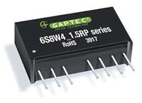
The 6S8W4_1.5 Series is an excellent performance and high power density design. The highest efficiency allows high operating temperatures up to 85°C. Features:
Download PCB Footprints and Schematic Symbols for free, to download/request, please click the Logo on the right in the below Selection Guide.
| |||||||||||||||||||||||||||||||||||||||||||||||||||||||||||||||||||||||||||||||||||||||||||||||||||||||||||||||||||||||||||||||||||||||||||||||||||||||||||||||||||||||||||||||||||||||||||||||||||||||||
| 6S8W4_1.6RP | SIP8 | 4:1 | 9-36 | 3.3; 5; 9; 12; 15; 24 | 1.6 | • | • | 88% | -40°C - +85°C | UL62368 | 6S8W4_1.6RP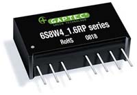
The 6S8W4_1.6 Series is an excellent performance and high power density design. The highest efficiency allows high operating temperatures up to 105°C. Features:
Download PCB Footprints and Schematic Symbols for free, to download/request, please click the Logo on the right in the below Selection Guide.
| ||||||||||||||||||||||||||||||||||||||||||||||||||||||||||||||||||||||||||||||||||||||||||||||||||||||||||||||||||||||||||||||||||||||||||||||||||||||||||||||||||||||||||||||||||||||||||||||||||||||||
| 6S8W4_3RP | SIP8 | 4:1 | 9-36; 18-75 | 3.3; 5; 9; 12; 15; 24; ±5; ±12; ±15 | 3 | • | • | 87% | -40°C - +85°C | 6S8W4_3RP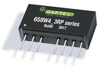
The 6S8W4_3 Series is an excellent performance and high power density design, with high isolation. Features:
Download PCB Footprints and Schematic Symbols for free, to download/request, please click the Logo on the right in the below Selection Guide.
| |||||||||||||||||||||||||||||||||||||||||||||||||||||||||||||||||||||||||||||||||||||||||||||||||||||||||||||||||||||||||||||||||||||||||||||||||||||||||||||||||||||||||||||||||||||||||||||||||||||||||
| 6DAW_1.5 | DIP24 | 2:1 | 9-18; 18-36; 36-72 | 5; 9; 12; 15; 24; ±9; ±12; ±15; ±24 | 1.5 | • | • | 87% | -40°C - +85°C | 6DAW_1.5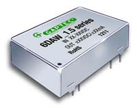
The 6DAW_1.5 series are specially designed for applications where a wide range input voltage power supplies are isolated from the input power supply in a distributed power supply system on a circuit board. Features:
Download PCB Footprints and Schematic Symbols for free, to download/request, please click the Logo on the right in the below Selection Guide.
| |||||||||||||||||||||||||||||||||||||||||||||||||||||||||||||||||||||||||||||||||||||||||||||||||||||||||||||||||||||||||||||||||||||||||||||||||||||||||||||||||||||||||||||||||||||||||||||||||||||||||
| 6D6AW_1.5 | DIP | 2:1 | 9-18; 18-36 | 3.3; 5; 12; 15 | 1.5 | • | • | 86% | -40°C - +85°C | 6D6AW_1.5
The 6D6AW_1.5 series are specially designed for applications where a wide range input voltage power supplies are isolated from the input power supply in a distributed power supply system on a circuit board. Features:
Download PCB Footprints and Schematic Symbols for free, to download/request, please click the Logo on the right in the below Selection Guide.
| |||||||||||||||||||||||||||||||||||||||||||||||||||||||||||||||||||||||||||||||||||||||||||||||||||||||||||||||||||||||||||||||||||||||||||||||||||||||||||||||||||||||||||||||||||||||||||||||||||||||||
| 6DAW4_1.5 | DIP24 | 4:1 | 9-36; 18-75 | 3.3; 5; 9; 12; 15; ±5; ±12; ±15 | 1.5 | • | • | 88% | -40°C - +85°C | UL60950 | 6DAW4_1.5
The 6DAW4_1.5 series are specially designed for applications where a wide range input voltage power supplies are isolated from the input power supply in a distributed power supply system on a circuit board. Features:
Download PCB Footprints and Schematic Symbols for free, to download/request, please click the Logo on the right in the below Selection Guide.
| ||||||||||||||||||||||||||||||||||||||||||||||||||||||||||||||||||||||||||||||||||||||||||||||||||||||||||||||||||||||||||||||||||||||||||||||||||||||||||||||||||||||||||||||||||||||||||||||||||||||||
| 6DMW_1.5 | 1“x1“ | 2:1 | 9-18; 18-36 | 5; 12; 15; 24; ±5; ±12; ±15 | 1.5 | • | • | 87% | -40°C - +85°C | UL60950 | 6DMW_1.5
The 6DMW series products are of 6W output power, wide range of voltage input of 9-18VDC, 18-36VDC, isolation voltage of 1500VDC, output over-voltage protection and output short circuit protection with the bare component in compliance with CISPR22/EN55022 CLASS A; these products are widely used in fields such as Medical care, industrial control, electric power, instruments and communication. Features:
Download PCB Footprints and Schematic Symbols for free, to download/request, please click the Logo on the right in the below Selection Guide.
| ||||||||||||||||||||||||||||||||||||||||||||||||||||||||||||||||||||||||||||||||||||||||||||||||||||||||||||||||||||||||||||||||||||||||||||||||||||||||||||||||||||||||||||||||||||||||||||||||||||||||
| 6DMW4_1.5 | 1“x1“ | 4:1 | 9-36; 18-75 | 5; 9; 12; 15; 24; ±5; ±12; ±15; ±24 | 1.5 | • | • | 88% | -40°C - +85°C | UL60950 | 6DMW4_1.5
The 6DMW4 series products are of 6W output power, wide range of voltage input of 9-36VDC, 18-75VDC, isolation voltage of 1500VDC, output over-voltage protection and output short circuit protection with the bare component in compliance with CISPR22/EN55022 CLASS A; these products are widely used in fields such as Medical care, industrial control, electric power, instruments and communication. Features:
Download PCB Footprints and Schematic Symbols for free, to download/request, please click the Logo on the right in the below Selection Guide.
| ||||||||||||||||||||||||||||||||||||||||||||||||||||||||||||||||||||||||||||||||||||||||||||||||||||||||||||||||||||||||||||||||||||||||||||||||||||||||||||||||||||||||||||||||||||||||||||||||||||||||
| 6DMRW4_2.25 | 1“x1“ | 4:1 | 40-160 | 5; 12; 15; 24 | 2.25 | • | • | 86% | -40°C - +85°C | 6DMRW4_2.25
The 6DMRW4_2.25 series are isolated 6W DC/DC converters. Designed with high efficiency they allow the operating temperature range of these units to be -40°C to +85°C (with derating). Meets requirements of railway standard EN50155 Features:
These converters are well suitable for:
Download PCB Footprints and Schematic Symbols for free, to download/request, please click the Logo on the right in the below Selection Guide.
| |||||||||||||||||||||||||||||||||||||||||||||||||||||||||||||||||||||||||||||||||||||||||||||||||||||||||||||||||||||||||||||||||||||||||||||||||||||||||||||||||||||||||||||||||||||||||||||||||||||||||
| 6DAW4_3 | DIP24 | 4:1 | 9-36; 18-72 | 3.3; 5; 9; 12; 15; 24; ±5; ±12; ±15 | 3 | • | • | 88% | -40°C - +85°C | UL60950 | 6DAW4_3
The 6DAW4_3 series are specially designed for applications where a wide range input voltage power supplies are isolated from the input power supply in a distributed power supply system on a circuit board. Features:
Download PCB Footprints and Schematic Symbols for free, to download/request, please click the Logo on the right in the below Selection Guide.
| ||||||||||||||||||||||||||||||||||||||||||||||||||||||||||||||||||||||||||||||||||||||||||||||||||||||||||||||||||||||||||||||||||||||||||||||||||||||||||||||||||||||||||||||||||||||||||||||||||||||||
| 6DAMW4_6 | DIP24 | 4:1 | 9-36; 18-72 | 5; 9; 12; 15; 24; | 6 | • | • | 85% | -40°C - +85°C | 6DAMW4_6
The 6DAMW4_6 series are specially designed for applications where a wide range input voltage power supplies are isolated from the input power supply in a distributed power supply system on a circuit board. Features:
Download PCB Footprints and Schematic Symbols for free, to download/request, please click the Logo on the right in the below Selection Guide.
|
Series |
Case Size |
Input Range |
Input Voltage (VDC) |
Output Voltage (VDC) |
Output Current (A) |
Isolation (kVDC) |
Regulation |
SCP * |
η max. |
Operating Temp. |
Dimming |
Certs |
||||||||||||||||||||||||||||||||||||||||||||||||||||||||||||||||||||||||||||||||||||||||||||||||||||||||||||||||||||||||||||||||||||||||||||||||||||||||||||||||||||||||||||||||||||||||||||||||||||||||||||||
| 7.5DAW_2 | DIP24 | 2:1 | 9-18; 18-36; 36-75 | 3.3; 5; 9; 12; 15; 24; ±5; ±9; ±12; ±15; ±24 | 2; 3 | • | • | 87% | -40°C - +100°C | 7.5DAW_2
The 7.5DAW_2 & 7.5DAW_3 series are specially designed for applications where a wide range input voltage power supplies are isolated from the input power supply in a distributed power supply system on a circuit board. Features:
Download PCB Footprints and Schematic Symbols for free, to download/request, please click the Logo on the right in the below Selection Guide.
|
Series |
Case Size |
Input Range |
Input Voltage (VDC) |
Output Voltage (VDC) |
Output Current (A) |
Isolation (kVDC) |
Regulation |
SCP * |
η max. |
Operating Temp. |
Dimming |
Certs |
||||||||||||||||||||||||||||||||||||||||||||||||||||||||||||||||||||||||||||||||||||||||||||||||||||||||||||||||||||||||||||||||||||||||||||||||||||||||
| 8DPW_1.6 | DIP24 | 2:1 | 4.5-9; 9-18; 18-36; 36-72 | 3.3; 5; 12; 15; ±5; ±12; ±15 | 1.6 | • | • | 86% | -40°C - +85°C | 8DPW_1.6
The 8DPW_1.6 Series are isolated 8W DC/DC converters. Designed with high efficiency in a 24 pin DIP package with industry-standard footprint. Further features include:
These converters are well suitable for:
Everywhere where isolated, tightly regulated voltages and compact size are required.
Download PCB Footprints and Schematic Symbols for free, to download/request, please click the Logo on the right in the below Selection Guide.
| |||||||||||||||||||||||||||||||||||||||||||||||||||||||||||||||||||||||||||||||||||||||||||||||||||||||||||||||||||||||||||||||||||||||||||||||||||||||||
| 8DPW4_1.6 | DIP24 | 4:1 | 9-36; 18-75 | 3.3; 5; 12; 15; ±5; ±12; ±15 | 1.6 | • | • | 86% | -40°C - +85°C | 8DPW4_1.6
The 8DPW4_1.6 Series are isolated 8W DC/DC converters. Designed with high efficiency in a 24 pin DIP package with industry-standard footprint. Further features include:
These converters are well suitable for:
Everywhere where isolated. tightly regulated voltages and compact size are required.
Download PCB Footprints and Schematic Symbols for free, to download/request, please click the Logo on the right in the below Selection Guide.
| |||||||||||||||||||||||||||||||||||||||||||||||||||||||||||||||||||||||||||||||||||||||||||||||||||||||||||||||||||||||||||||||||||||||||||||||||||||||||
| 8DPRW4_3 | DIP24 | 4:1 | 13-70; 42-176 | 3.3; 5; 12; 15; ±5; ±12; ±15 | 3 | • | • | 86% | -40°C - +85°C | 8DPRW4_3
The 8DPRW4_3 Series are isolated 8W DC/DC converters. Designed with high efficiency in a 24 pin DIP package with industry-standard footprint. Further features include:
These converters are well suitable for:
Download PCB Footprints and Schematic Symbols for free, to download/request, please click the Logo on the right in the below Selection Guide.
|
Series |
Case Size |
Input Range |
Input Voltage (VDC) |
Output Voltage (VDC) |
Output Current (A) |
Isolation (kVDC) |
Regulation |
SCP * |
η max. |
Operating Temp. |
Dimming |
Certs |
||||||||||||||||||||||||||||||||||||||||||||||||||||||||||||||||||||||||||||||||||||||||||||||||||||||||||||||||||||||||||||||||||||||||||||||||||||||||||||||||||||||||||
| 9S8W_1.6RP | SIP8 | 2:1 | 9-18; 18-36; 36-75 | 3.3; 5; 9; 12; 15; 24; ±5; ±12; ±15 | 1.6 | • | • | 90% | -40°C - +85°C | UL62368 | 9S8W_1.6RP
Download PCB Footprints and Schematic Symbols for free, to download/request, please click the Logo on the right in the below Selection Guide.
| ||||||||||||||||||||||||||||||||||||||||||||||||||||||||||||||||||||||||||||||||||||||||||||||||||||||||||||||||||||||||||||||||||||||||||||||||||||||||||||||||||||||||||
| 9S8W4E_1.6RP | SIP8 | 4:1 | 9-36; 18-75 | 3.3; 5; 9; 12; 15; 24; ±5; ±12; ±15 | 1.6 | • | • | 89% | -40°C - +100°C | 9S8W4E_1.6RP
The 9S8W4E_ cost effective series is an excellent performance and high power density design with wide range devices operate over 4:1 input voltage range. Features:
Download PCB Footprints and Schematic Symbols for free, to download/request, please click the Logo on the right in the below Selection Guide.
| |||||||||||||||||||||||||||||||||||||||||||||||||||||||||||||||||||||||||||||||||||||||||||||||||||||||||||||||||||||||||||||||||||||||||||||||||||||||||||||||||||||||||||
| 9S8W4_1.6RP | SIP8 | 4:1 | 9-36; 18-75 | 3.3; 5; 9; 12; 15; 24; ±5; ±12; ±15 | 1.6 | • | • | 89% | -40°C - +85°C | UL62368 | 9S8W4_1.6RP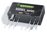
The 9S8W4_ series is an excellent performance and high power density design with wide range devices operate over 4:1 input voltage range. Features:
Download PCB Footprints and Schematic Symbols for free, to download/request, please click the Logo on the right in the below Selection Guide.
|
Series |
Case Size |
Input Range |
Input Voltage (VDC) |
Output Voltage (VDC) |
Output Current (A) |
Isolation (kVDC) |
Regulation |
SCP * |
η max. |
Operating Temp. |
Dimming |
Certs |
||||||||||||||||||||||||||||||||||||||||||||||||||||||||||||||||||||||||||||||||||||||||||||||||||||||||||||||||||||||||||||||||||||||||||||||||||||||||||||||||||||||||||||||||||||||
| 10S8W_1.5RP | SIP8 | 2:1 | 9-18; 18-36 | 3.3; 5; 9; 12; 15; 24 | 1.5 | • | • | 88% | -40°C - +85°C | 10S8W_1.5RP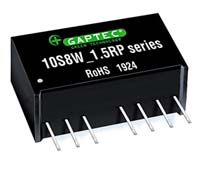
The 10S8W_1.5RP series is an excellent performance and high power density design with wide range devices operate over 2:1 input voltage range. Features:
Download PCB Footprints and Schematic Symbols for free, to download/request, please click the Logo on the right in the below Selection Guide.
| |||||||||||||||||||||||||||||||||||||||||||||||||||||||||||||||||||||||||||||||||||||||||||||||||||||||||||||||||||||||||||||||||||||||||||||||||||||||||||||||||||||||||||||||||||||||
| 10DPW_1.5 | DIP24 | 2:1 | 9-18; 18-36; 36-75 | 3.3; 5; 12; 15; ±5; ±12; ±15 | 1.5 | • | • | 83% | -40°C - +85°C | 10DPW_1.5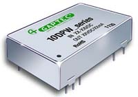
The 10DPW Series are isolated 10W DC/DC converters. Designed with high efficiency, they allow the operating temperature range of these units to be -40°C to +85°C with industry-standard footprint. Further features include wide 2:1 input voltage range, remote on/off control, short-circuit protection and over voltage protection. Features:
Field of application:
Download PCB Footprints and Schematic Symbols for free, to download/request, please click the Logo on the right in the below Selection Guide.
| |||||||||||||||||||||||||||||||||||||||||||||||||||||||||||||||||||||||||||||||||||||||||||||||||||||||||||||||||||||||||||||||||||||||||||||||||||||||||||||||||||||||||||||||||||||||
| 10DPW4_1.5 | DIP24 | 4:1 | 9-36; 18-75 | 3.3; 5; 12; 15; ±5; ±12; ±15 | 1.5 | • | • | 83% | -40°C - +85°C | 10DPW4_1.5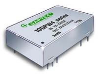
The 10DPW4 Series are isolated 10W DC/DC converters. Designed with high efficiency, they allow the operating temperature range of these units to be -40°C to +85°C with industry-standard footprint. Further features include wide 2:1 input voltage range, remote on/off control, short-circuit protection and over voltage protection. Features:
Field of application:
Download PCB Footprints and Schematic Symbols for free, to download/request, please click the Logo on the right in the below Selection Guide.
| |||||||||||||||||||||||||||||||||||||||||||||||||||||||||||||||||||||||||||||||||||||||||||||||||||||||||||||||||||||||||||||||||||||||||||||||||||||||||||||||||||||||||||||||||||||||
| 10DMW4_1.5 | 1“x1“ | 4:1 | 9-36; 18-75 | 3.3; 5; 9; 12; 15; 24; ±5; ±9; ±12; ±15; ±24 | 1.5 | • | • | 88% | -40°C - +85°C | UL60950 | 10DMW4_1.5
The 10DAW4 series, are specially designed for applications where a wide range input voltage power supplies are isolated from the input power supply in a distributed power supply system on a circuit board. Features:
Download PCB Footprints and Schematic Symbols for free, to download/request, please click the Logo on the right in the below Selection Guide.
| ||||||||||||||||||||||||||||||||||||||||||||||||||||||||||||||||||||||||||||||||||||||||||||||||||||||||||||||||||||||||||||||||||||||||||||||||||||||||||||||||||||||||||||||||||||||
| 10DMW4_DS1.5 | 1“x1“ | 4:1 | 18-75 | Vout1: 5 Vout2: 5; 12; 24 | 1.5 | • | • | 84% | -40°C - +85°C | 10DMW4_DS1.5
The 10DAW4_DS1.5 series, are specially designed for applications where a wide range input voltage power supplies are isolated from the input power supply in a distributed power supply system on a circuit board. Features:
Download PCB Footprints and Schematic Symbols for free, to download/request, please click the Logo on the right in the below Selection Guide.
| |||||||||||||||||||||||||||||||||||||||||||||||||||||||||||||||||||||||||||||||||||||||||||||||||||||||||||||||||||||||||||||||||||||||||||||||||||||||||||||||||||||||||||||||||||||||
| 10D6AW4_1.5 | DIP | 4:1 | 9-36 | 5; 12; 15 | 1.5 | • | • | 88% | -40°C - +85°C | 10D6AW4_1.5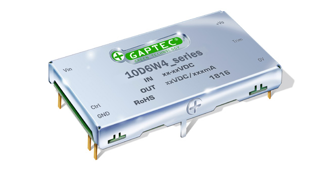
The 10D6AW4_1.5 series are specially designed for applications where a wide range input voltage power supplies are isolated from the input power supply in a distributed power supply system on a circuit board. Features:
Download PCB Footprints and Schematic Symbols for free, to download/request, please click the Logo on the right in the below Selection Guide.
| |||||||||||||||||||||||||||||||||||||||||||||||||||||||||||||||||||||||||||||||||||||||||||||||||||||||||||||||||||||||||||||||||||||||||||||||||||||||||||||||||||||||||||||||||||||||
| 10DAW_1.5 | 2“x1“ | 2:1 | 9-18; 18-36; 36-72 | 3.3; 5; 12; 15; 24; ±5; ±12; ±15; ±24 | 1.5 | • | • | 88% | -40°C - +85°C | 10DAW_1.5
The 10DAW series are specially designed for applications where a wide range input voltage power supplies are isolated from the input power supply in a distributed power supply system on a circuit board. Features:
Download PCB Footprints and Schematic Symbols for free, to download/request, please click the Logo on the right in the below Selection Guide.
| |||||||||||||||||||||||||||||||||||||||||||||||||||||||||||||||||||||||||||||||||||||||||||||||||||||||||||||||||||||||||||||||||||||||||||||||||||||||||||||||||||||||||||||||||||||||
| 10DAW4_1.5 | 2“x1“ | 4:1 | 9-36; 18-75 | 3.3; 5; 12; 15; 24; ±5; ±12; ±15 | 1.5 | • | • | 87% | -40°C - +85°C | 10DAW4_1.5
The 10DAW4 series, with wide input of 9-36VDC and 18-75VDC, are specially designed for applications where a wide range input voltage power supplies are isolated from the input power supply in a distributed power supply system on a circuit board. Features:
Download PCB Footprints and Schematic Symbols for free, to download/request, please click the Logo on the right in the below Selection Guide.
| |||||||||||||||||||||||||||||||||||||||||||||||||||||||||||||||||||||||||||||||||||||||||||||||||||||||||||||||||||||||||||||||||||||||||||||||||||||||||||||||||||||||||||||||||||||||
| 10DRW4_2.25 | 2“x1“ | 4:1 | 40-160 | 3.3; 5; 12; 15; 24 | 2.25 | • | • | 85% | -40°C - +85°C | 10DRW4_2.25
The 10DRW4_2.25 series are isolated 10W DC/DC converters. Designed with high efficiency they allow the operating temperature range of these units to be -40°C to +85°C (with derating). Meets requirements of railway standard EN50155 Features:
These converters are well suitable for:
Download PCB Footprints and Schematic Symbols for free, to download/request, please click the Logo on the right in the below Selection Guide.
| |||||||||||||||||||||||||||||||||||||||||||||||||||||||||||||||||||||||||||||||||||||||||||||||||||||||||||||||||||||||||||||||||||||||||||||||||||||||||||||||||||||||||||||||||||||||
| 10DAW4_3 | 2“x1“ | 4:1 | 9-36; 18-75 | 3.3; 9; 5; 12; 15; 24; ±5; ±12; ±15 | 3 | • | • | 88% | -40°C - +85°C | UL60950 | 10DAW4_3
The 10DAW4 series, with wide input of 9-36VDC and 18-75VDC, are specially designed for applications where a wide range input voltage power supplies are isolated from the input power supply in a distributed power supply system on a circuit board. Features:
Download PCB Footprints and Schematic Symbols for free, to download/request, please click the Logo on the right in the below Selection Guide.
|
Series |
Case Size |
Input Range |
Input Voltage (VDC) |
Output Voltage (VDC) |
Output Current (A) |
Isolation (kVDC) |
Regulation |
SCP * |
η max. |
Operating Temp. |
Dimming |
Certs |
||||||||||||||||||||||||||||||||||||||||||||||||||||||||||||||||||||||||||||||||||||||||||||||||||||||||||||||||||||||||||||||||||||||
| 12DPW_1.5 | DIP24 | 2:1 | 9-18; 18-36; 36-75 | 3.3; 5; 12; 15; ±5; ±12; ±15 | 1.5 | • | • | 83% | -40°C - +85°C | 12DPW_1.5
The 12DPW Series are isolated 12W DC/DC converters. Designed with high efficiency. they allow the operating temperature range of these units to be -40°C to +85°C in a 24 pin DIP package with industry-standard footprint. Further features include wide 2:1 input voltage range. remote on/off control. short-circuit protection and over voltage protection. These converters are well suitable for battery operated equipment. measurement equipment. telecom. wireless network and industry control systems. Everywhere where isolated. tightly regulated voltages and compact size are required.
Download PCB Footprints and Schematic Symbols for free, to download/request, please click the Logo on the right in the below Selection Guide.
| |||||||||||||||||||||||||||||||||||||||||||||||||||||||||||||||||||||||||||||||||||||||||||||||||||||||||||||||||||||||||||||||||||||||
| 12DPW4_1.5 | DIP24 | 4:1 | 9-36; 18-75 | 3.3; 5; 12; 15; ±5; ±12; ±15 | 1.5 | • | • | 83% | -40°C - +85°C | 12DPW4_1.5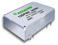
The 12DPW4 Series are isolated 12W DC/DC converters. Designed with high efficiency. they allow the operating temperature range of these units to be -40°C to +85°C in a 24 pin DIP package with industry-standard footprint. Further features include wide 2:1 input voltage range. remote on/off control. short-circuit protection and over voltage protection. These converters are well suitable for battery operated equipment. measurement equipment. telecom. wireless network and industry control systems. Everywhere where isolated. tightly regulated voltages and compact size are required.
Download PCB Footprints and Schematic Symbols for free, to download/request, please click the Logo on the right in the below Selection Guide.
|
Series |
Case Size |
Input Range |
Input Voltage (VDC) |
Output Voltage (VDC) |
Output Current (A) |
Isolation (kVDC) |
Regulation |
SCP * |
η max. |
Operating Temp. |
Dimming |
Certs |
||||||||||||||||||||||||||||||||||||||||||||||||||||||||||||||||||||||||||||||||||||||||||||||||||||||||||||||||||||||||||||||||||||||
| 15DPW_1.6 | DIP24 | 2:1 | 9-18; 18-36; 36-75 | 3.3; 5; 12; 15; ±5; ±12; ±15 | 1.6 | • | • | 90% | -40°C - +85°C | 15DPW_1.6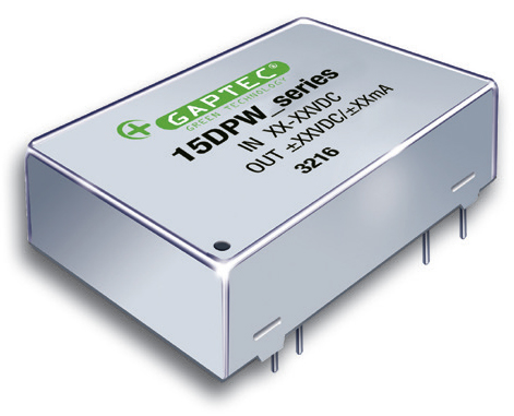
The 15DPW_1.6 series are high performance 15W single & dual output DC-DC converters. These converters are consisted with nickle-coated copper DIP package with high performance features such as synchronis rectfication and tight line load regulation. Features:
Download PCB Footprints and Schematic Symbols for free, to download/request, please click the Logo on the right in the below Selection Guide.
| |||||||||||||||||||||||||||||||||||||||||||||||||||||||||||||||||||||||||||||||||||||||||||||||||||||||||||||||||||||||||||||||||||||||
| 15DPW4_1.6 | DIP24 | 4:1 | 9-36; 18-75 | 3.3; 5; 12; 15; ±5; ±12; ±15 | 1.6 | • | • | 90% | -40°C - +85°C | 15DPW4_1.6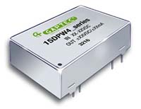
The 15DPW_1.6 series are high performance 15W single & dual output DC-DC converters. These converters are consisted with nickle-coated copper DIP package with high performance features such as synchronis rectfication and tight line load regulation. Features:
Download PCB Footprints and Schematic Symbols for free, to download/request, please click the Logo on the right in the below Selection Guide.
| |||||||||||||||||||||||||||||||||||||||||||||||||||||||||||||||||||||||||||||||||||||||||||||||||||||||||||||||||||||||||||||||||||||||
| 15DMWE_1.5 | 1“x1“ | 2:1 | 9-18; 18-36; 36-75 | 3.3; 5; 12; 15; 24 | 1.5 | • | • | 91% | -40°C - +105°C | 15DMWE_1.5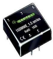
The 15DMWE_1.5 series are isolated cost effective 15W DC/DC converters. Designed with high efficiency and industry-standard 1"x1" footprint. Features:
Download PCB Footprints and Schematic Symbols for free, to download/request, please click the Logo on the right in the below Selection Guide.
| |||||||||||||||||||||||||||||||||||||||||||||||||||||||||||||||||||||||||||||||||||||||||||||||||||||||||||||||||||||||||||||||||||||||
| 15DMW_1.5 | 1“x1“ | 2:1 | 9-18; 18-36; 36-75 | 3.3; 5; 12; 15; ±12; ±15 | 1.5 | • | • | 89% | -40°C - +85°C | 15DMW_1.5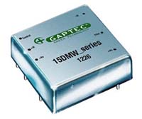
The 15DMW_1.5 series are isolated 15W DC/DC converters. Designed with high efficiency. they allow the operating temperature range of these units to be -40°C to +85°C (with derating) with industry-standard footprint. Features:
These converters are well suitable for:
Download PCB Footprints and Schematic Symbols for free, to download/request, please click the Logo on the right in the below Selection Guide.
| |||||||||||||||||||||||||||||||||||||||||||||||||||||||||||||||||||||||||||||||||||||||||||||||||||||||||||||||||||||||||||||||||||||||
| 15DMOW4_1.5 | 1“x1“ | 4:1 | 18-75 | 3.3; 12 | 1.5 | • | • | 88,5% | -40°C - +85°C | 15DMOW4_1.5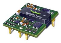
The 15DMOW4_S1.5 series are isolated 15W DC/DC open frame converters. Designed with high efficiency. they allow the operating temperature range of these units to be -40°C to +105°C (with derating) with industry-standard footprint. Features:
These converters are well suitable for:
Download PCB Footprints and Schematic Symbols for free, to download/request, please click the Logo on the right in the below Selection Guide.
| |||||||||||||||||||||||||||||||||||||||||||||||||||||||||||||||||||||||||||||||||||||||||||||||||||||||||||||||||||||||||||||||||||||||
| 15DMWE4_S1.5 | 1“x1“ | 4:1 | 9-36; 18-75 | 3.3; 5; 12; 15; 24 | 1.5 | • | • | 91% | -40°C - +105°C | UL62368 | 15DMWE4_S1.5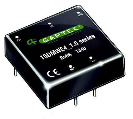
The 15DMWE4_S1.5 series are isolated 15W DC/DC cost effective converters. Designed with high efficiency. they allow the operating temperature range of these units to be -40°C to +105°C (with derating) with industry-standard footprint. Features:
These converters are well suitable for:
Download PCB Footprints and Schematic Symbols for free, to download/request, please click the Logo on the right in the below Selection Guide.
| ||||||||||||||||||||||||||||||||||||||||||||||||||||||||||||||||||||||||||||||||||||||||||||||||||||||||||||||||||||||||||||||||||||||
| 15DMWE4_D1.5 | 1“x1“ | 4:1 | 9-36; 18-75 | ±5; ±12; ±15; ±24 | 1.5 | • | • | 90% | -40°C - +105°C | 15DMWE4_D1.5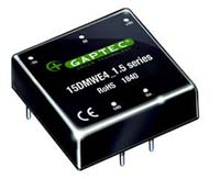
The 15DMWE4_D1.5 series are isolated 15W DC/DC cost effective converters. Designed with high efficiency. they allow the operating temperature range of these units to be -40°C to +105°C (with derating) with industry-standard footprint. Features:
These converters are well suitable for:
Download PCB Footprints and Schematic Symbols for free, to download/request, please click the Logo on the right in the below Selection Guide.
| |||||||||||||||||||||||||||||||||||||||||||||||||||||||||||||||||||||||||||||||||||||||||||||||||||||||||||||||||||||||||||||||||||||||
| 15DMW4_1.5 | 1“x1“ | 4:1 | 9-36; 18-75 | 3.3; 5; 12; 15; ±12; ±15 | 1.5 | • | • | 88% | -40°C - +85°C | 15DMW4_1.5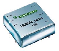
The 15DMW4_1.5 series are isolated 15W DC/DC converters. Designed with high efficiency. they allow the operating temperature range of these units to be -40°C to +85°C (with derating) with industry-standard footprint. Features:
These converters are well suitable for:
Download PCB Footprints and Schematic Symbols for free, to download/request, please click the Logo on the right in the below Selection Guide.
| |||||||||||||||||||||||||||||||||||||||||||||||||||||||||||||||||||||||||||||||||||||||||||||||||||||||||||||||||||||||||||||||||||||||
| 15DAWE_1.5 | 2“x1“ | 2:1 | 18-36; 36-75 | 3.3; 5; 12; 15; 24 | 1.5 | • | • | 90% | -40°C - +85°C | UL60950 | 15DAWE_1.5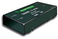
The 15DAWE_1.5 series offer 15W of output. with 2:1 wide input voltage of 18-36VDC and 36-75VDC. and features:
All models are particularly suited to industrial. tele-communications. test equipments power.
Download PCB Footprints and Schematic Symbols for free, to download/request, please click the Logo on the right in the below Selection Guide.
| ||||||||||||||||||||||||||||||||||||||||||||||||||||||||||||||||||||||||||||||||||||||||||||||||||||||||||||||||||||||||||||||||||||||
| 15DAW4_1.5 | 2“x1“ | 4:1 | 9-36; 18-75 | 3.3; 5; 12; 15; 24; ±5; ±12; ±15 | 1.5 | • | • | 90% | -40°C - +85°C | 15DAW4_1.5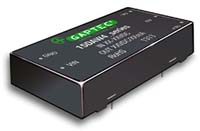
The 15DAW4_1.5 series offer 15W of output. with 2:1 wide input voltage of 9-18VDC. 18-36VDC and 36-75VDC. and features:
All models are particularly suited to industrial. tele-communications. test equipments power.
Download PCB Footprints and Schematic Symbols for free, to download/request, please click the Logo on the right in the below Selection Guide.
| |||||||||||||||||||||||||||||||||||||||||||||||||||||||||||||||||||||||||||||||||||||||||||||||||||||||||||||||||||||||||||||||||||||||
| 15DRW4_2.25 | 2“x1“ | 4:1 | 40-160 | 3.3; 5; 12; 15; 24 | 2.25 | • | • | 86% | -40°C - +85°C | UL62368 | 15DRW4_2.25
The 15DRW4_2.25 series are isolated 15W DC/DC converters. Designed with high efficiency they allow the operating temperature range of these units to be -40°C to +85°C (with derating). Meets requirements of railway standard EN50155 Features:
These converters are well suitable for:
Download PCB Footprints and Schematic Symbols for free, to download/request, please click the Logo on the right in the below Selection Guide.
|
Series |
Case Size |
Input Range |
Input Voltage (VDC) |
Output Voltage (VDC) |
Output Current (A) |
Isolation (kVDC) |
Regulation |
SCP * |
η max. |
Operating Temp. |
Dimming |
Certs |
||||||||||||||||||||||||||||||||||||||||||||||||||||||||||||||||||||||||||||||||||||||||||||||||||||||||||||||||||||||||||||||||||||||||||||||||||
| 20DMW_1.5 | 1“x1“ | 2:1 | 9-18; 18-36; 36-75 | 3.3; 5; 12; 15; ±12; ±15 | 1.5 | • | • | 90% | -40°C - +85°C | 20DMW_1.5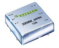
The 20DMW_1.5 series are isolated 20W DC/DC converters. Designed with high efficiency. they allow the operating temperature range of these units to be -40°C to +85°C (with derating) with industry-standard footprint. Features:
These converters are well suitable for:
Download PCB Footprints and Schematic Symbols for free, to download/request, please click the Logo on the right in the below Selection Guide.
| |||||||||||||||||||||||||||||||||||||||||||||||||||||||||||||||||||||||||||||||||||||||||||||||||||||||||||||||||||||||||||||||||||||||||||||||||||
| 20DMWE_1.5 | 1“x1“ | 2:1 | 9-18; 18-36; 36-75 | 3.3; 5; 12; 15; 24 | 1.5 | • | • | 91% | -40°C - +105°C | 20DMWE_1.5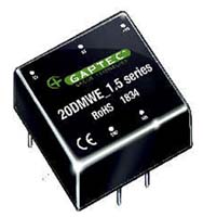
The 20DMWE_1.5 series are isolated cost effective 20W DC/DC converters. Designed with high efficiency and industry-standard 1"x1" footprint. Features:
Download PCB Footprints and Schematic Symbols for free, to download/request, please click the Logo on the right in the below Selection Guide.
| |||||||||||||||||||||||||||||||||||||||||||||||||||||||||||||||||||||||||||||||||||||||||||||||||||||||||||||||||||||||||||||||||||||||||||||||||||
| 20DMW4_1.5 | 1“x1“ | 4:1 | 9-36; 18-75 | 3.3; 5; 12; 15; ±12; ±15 | 1.5 | • | • | 90% | -40°C - +85°C | 20DMW4_1.5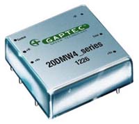
The 20DMW4_1.5 series are isolated 20W DC/DC converters. Designed with high efficiency. they allow the operating temperature range of these units to be -40°C to +85°C (with derating) with industry-standard footprint. Features:
These converters are well suitable for:
Download PCB Footprints and Schematic Symbols for free, to download/request, please click the Logo on the right in the below Selection Guide.
| |||||||||||||||||||||||||||||||||||||||||||||||||||||||||||||||||||||||||||||||||||||||||||||||||||||||||||||||||||||||||||||||||||||||||||||||||||
| 20DMWE4_1.5 | 1“x1“ | 4:1 | 9-36; 18-75 | 3.3; 5; 12; 15 | 1.5 | • | • | 91% | -40°C - +105°C | UL62368 | 20DMWE4_1.5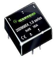
The 20DMWE4_1.5 series are isolated cost effective 20W DC/DC converters. Designed with high efficiency and industry-standard 1"x1" footprint. Features:
Download PCB Footprints and Schematic Symbols for free, to download/request, please click the Logo on the right in the below Selection Guide.
| ||||||||||||||||||||||||||||||||||||||||||||||||||||||||||||||||||||||||||||||||||||||||||||||||||||||||||||||||||||||||||||||||||||||||||||||||||
| 20DAWE_1.5 | 2“x1“ | 2:1 | 9-18; 18-36; 36-75 | 3.3; 5; 9; 12; 15; 24; 110; ±5; ±9; ±12; ±15; ±24 | 1.5 | • | • | 90% | -40°C - +85°C | UL60950 | 20DAWE_1.5
The 20DAWE_1.5 series offer 20W of output. with 2:1 wide input voltage of 9-18VDC, 18-36VDC and 36-75VDC Features:
All models are are applied to wide voltage range input situation such as:
Download PCB Footprints and Schematic Symbols for free, to download/request, please click the Logo on the right in the below Selection Guide.
| ||||||||||||||||||||||||||||||||||||||||||||||||||||||||||||||||||||||||||||||||||||||||||||||||||||||||||||||||||||||||||||||||||||||||||||||||||
| 20DAW4_1.5 | 2“x1“ | 4:1 | 9-36; 18-75 | 3.3; 5; 9; 12; 15; 24; ±5; ±9; ±12; ±15 | 1.5 | • | • | 90% | -40°C - +85°C | UL60950 | 20DAW4_1.5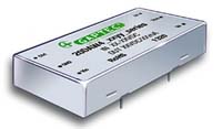
The 20DAW_1.5 series offer 20W of output with 4:1 wide input voltage of 9-36Vdc & 18-75VDC Features:
All models are are applied to wide voltage range input situation such as:
Download PCB Footprints and Schematic Symbols for free, to download/request, please click the Logo on the right in the below Selection Guide.
| ||||||||||||||||||||||||||||||||||||||||||||||||||||||||||||||||||||||||||||||||||||||||||||||||||||||||||||||||||||||||||||||||||||||||||||||||||
| 20DAW4_3 | 2“x1“ | 4:1 | 9-36; 18-75 | 3.3; 5; 9; 12; 15; 24 | 3 | • | • | 89% | -40°C - +85°C | UL60950 | 20DAW4_3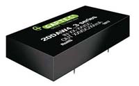
20DAW4_3 series are isolated 20W DC-DC products with 4:1 input voltage. EMI meets CISPR22/EN55022 CLASS A Features:
Field Application:
Download PCB Footprints and Schematic Symbols for free, to download/request, please click the Logo on the right in the below Selection Guide.
| ||||||||||||||||||||||||||||||||||||||||||||||||||||||||||||||||||||||||||||||||||||||||||||||||||||||||||||||||||||||||||||||||||||||||||||||||||
| 20DRW4_2.25 | 2“x1“ | 4:1 | 40-160 | 3.3; 5; 12; 15; 24 | 2.25 | • | • | 86% | -40°C - +85°C | 20DRW4_2.25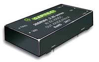
The 20DRW4_2.25 series are isolated 20W DC/DC converters. Designed with high efficiency they allow the operating temperature range of these units to be -40°C to +85°C (with derating). Meets requirements of railway standard EN50155 Features:
These converters are well suitable for:
Download PCB Footprints and Schematic Symbols for free, to download/request, please click the Logo on the right in the below Selection Guide.
| |||||||||||||||||||||||||||||||||||||||||||||||||||||||||||||||||||||||||||||||||||||||||||||||||||||||||||||||||||||||||||||||||||||||||||||||||||
| 20DBW8_1.5 | 2“x1,6“ | 8:1 | 6-50 | 5 | 1.5 | • | • | 90% | -40°C - +85°C | 20DBW8_1.5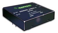
The 20DBW8_1.5 series offer 20W of output. with 8:1 ultra wide input voltage of 6-50VDC Features:
All models are are applied to wide voltage range input situation such as:
Download PCB Footprints and Schematic Symbols for free, to download/request, please click the Logo on the right in the below Selection Guide.
|
Series |
Case Size |
Input Range |
Input Voltage (VDC) |
Output Voltage (VDC) |
Output Current (A) |
Isolation (kVDC) |
Regulation |
SCP * |
η max. |
Operating Temp. |
Dimming |
Certs |
||||||||||||||
| 25DMOW_1.5 | 15.24 x 19.1 | 2:1 | 36-75 | 5 | 1.5 | • | • | 88% | -40°C - +85°C | UL60950 | 25DMOW_1.5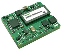
The 25DMOW_1.5 series offer 25W of output. with 2:1 wide input voltage of 36-75VDC Features:
All models are particularly suited to
Download PCB Footprints and Schematic Symbols for free, to download/request, please click the Logo on the right in the below Selection Guide.
|
Series |
Case Size |
Input Range |
Input Voltage (VDC) |
Output Voltage (VDC) |
Output Current (A) |
Isolation (kVDC) |
Regulation |
SCP * |
η max. |
Operating Temp. |
Dimming |
Certs |
||||||||||||||||||||||||||||||||||||||||||||||||||||||||||||||||||||||||||||||||||||||||||||||||||||||||||||||||||||
| 30DAWE_1.5 | 2“x1“ | 2:1 | 18-36; 36-75 | 3.3; 5; 12; 15; 24 | 1.5 | • | • | 89% | -40°C - +85°C | UL60950 | 30DAWE_1.5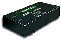
The 30DAWE_1.5 series offer 30W of output. with 2:1 wide input voltage of 18-36VDC & 36-75VDC Features:
All models are particularly suited to
Download PCB Footprints and Schematic Symbols for free, to download/request, please click the Logo on the right in the below Selection Guide.
| ||||||||||||||||||||||||||||||||||||||||||||||||||||||||||||||||||||||||||||||||||||||||||||||||||||||||||||||||||||
| 30DMWE4_1.5 | 1“x1“ | 4:1 | 9-36; 18-75 | 3.3; 5; 12; 15; 24; ±12; ±15; ±24 | 1.5 | • | • | 92% | -40°C - +80°C | 30DMWE4_1.5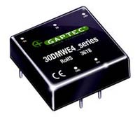
The 30DMWE4_1.5 series are isolated cost effective 30W DC/DC converters. Designed with high efficiency. They allow the operating temperature range of these units to be -40°C to +80°C (with derating) with industry-standard footprint. Features:
Download PCB Footprints and Schematic Symbols for free, to download/request, please click the Logo on the right in the below Selection Guide.
| |||||||||||||||||||||||||||||||||||||||||||||||||||||||||||||||||||||||||||||||||||||||||||||||||||||||||||||||||||||
| 30DMW_1.6 | 1“x1“ | 2:1 | 9-18; 18-36; 36-75 | 3.3; 5; 12; 15; ±12; ±15 | 1.6 | • | • | 88% | -40°C - +100°C | UL60950 | 30DMW_1.6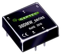
The 30DMW_1.6 series are isolated 30W DC/DC converters. Designed with high efficiency. They allow the operating temperature range of these units to be -40°C to +100°C (with derating) with industry-standard footprint. Features:
These converters are well suitable for:
Download PCB Footprints and Schematic Symbols for free, to download/request, please click the Logo on the right in the below Selection Guide.
| ||||||||||||||||||||||||||||||||||||||||||||||||||||||||||||||||||||||||||||||||||||||||||||||||||||||||||||||||||||
| 30DMW4_1.5 | 1“x1“ | 4:1 | 18-75 | 5; 12; 15; 24 | 1.5 | • | • | 92% | -40°C - +85°C | UL62368 | 30DMW4_1.5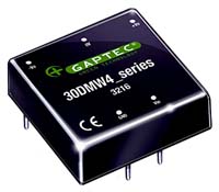
The 30DMW4_1.5 series are isolated 30W DC/DC converters. Designed with high efficiency. They allow the operating temperature range of these units to be -40°C to +85°C (with derating) with industry-standard footprint. Features:
These converters are well suitable for:
Download PCB Footprints and Schematic Symbols for free, to download/request, please click the Logo on the right in the below Selection Guide.
| ||||||||||||||||||||||||||||||||||||||||||||||||||||||||||||||||||||||||||||||||||||||||||||||||||||||||||||||||||||
| 30DMW4_1.6 | 1“x1“ | 4:1 | 9-36; 18-75 | 3.3; 5; 12; 15; ±12; ±15 | 1.6 | • | • | 92% | -40°C - +75°C | UL60950 | 30DMW4_1.6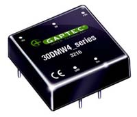
The 30DMW4_1.6 series are isolated 30W DC/DC converters. Designed with high efficiency. They allow the operating temperature range of these units to be -40°C to +85°C (with derating) with industry-standard footprint. Features:
These converters are well suitable for:
Download PCB Footprints and Schematic Symbols for free, to download/request, please click the Logo on the right in the below Selection Guide.
| ||||||||||||||||||||||||||||||||||||||||||||||||||||||||||||||||||||||||||||||||||||||||||||||||||||||||||||||||||||
| 30DAW4_1.5 | 2“x1“ | 4:1 | 9-36; 18-75 | 3.3; 5; 12; 15; ±12; ±15 | 1.5 | • | • | 88% | -40°C - +85°C | UL62368 | 30DAW4_1.5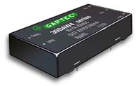
The 30DAW4_1.5 series offer 30W of output with wide input voltage of 9-36VDC & 18-75VDC Features:
All models are particularly suited to
Download PCB Footprints and Schematic Symbols for free, to download/request, please click the Logo on the right in the below Selection Guide.
| ||||||||||||||||||||||||||||||||||||||||||||||||||||||||||||||||||||||||||||||||||||||||||||||||||||||||||||||||||||
| 30DBW4_1.5 | 2“x1.6“ | 4:1 | 9-36; 18-75 | 3.3; 5; 9; 12; 15; 24 | 1.5 | • | • | 89% | -40°C - +75°C | 30DBW4_1.5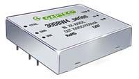
The 30DBW4_1.5 series offer 30W of output. wide input voltage of 9-36VDC & 18-75VDC Features:
All models are particularly suited to:
Download PCB Footprints and Schematic Symbols for free, to download/request, please click the Logo on the right in the below Selection Guide.
| |||||||||||||||||||||||||||||||||||||||||||||||||||||||||||||||||||||||||||||||||||||||||||||||||||||||||||||||||||||
| 30B16FW_1.5 | 1/16 Brick | 2:1 | 36-75 | 3.3 | 1.5 | • | • | 91% | -40°C - +85°C | UL60950 | 30B16FW_1.5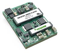
The 30B16FW_1.5 series offer 30W of output. with 2:1 wide input voltage of 36-75VDC Features:
All models are particularly suited to
Download PCB Footprints and Schematic Symbols for free, to download/request, please click the Logo on the right in the below Selection Guide.
|
Series |
Case Size |
Input Range |
Input Voltage (VDC) |
Output Voltage (VDC) |
Output Current (A) |
Isolation (kVDC) |
Regulation |
SCP * |
η max. |
Operating Temp. |
Dimming |
Certs |
||||||||||||||||||||||||||||||||||||||||||||||||||||||||||||||||||||||||||||||||||||||||||||||||||||||||||||||||||||
| 40DAWE_1.5 | 2“x1“ | 2:1 | 18-36; 36-75 | 12; 15; 24 | 1.5 | • | • | 91% | -40°C - +85°C | UL62368 | 40DAWE_1.5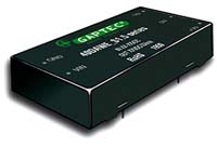
The 40DAWE_1.5 series are specially designed for applications where a wide range input voltage power supplies are isolated from the input power supply in a distributed power supply system on a circuit board. Features:
Application Field:
Download PCB Footprints and Schematic Symbols for free, to download/request, please click the Logo on the right in the below Selection Guide.
| ||||||||||||||||||||||||||||||||||||||||||||||||||||||||||||||||||||||||||||||||||||||||||||||||||||||||||||||||||||
| 40DAW_1.5 | 2“x1“ | 2:1 | 9-18; 18-36; 36-75 | 3.3; 5; 12; 15; ±12; ±15 | 1.5 | • | • | 91% | -40°C - +85°C | 40DAW_1.5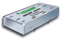
The 40DAW_1.5 series are specially designed for applications where a wide range input voltage power supplies are isolated from the input power supply in a distributed power supply system on a circuit board. Features:
Application Field:
Download PCB Footprints and Schematic Symbols for free, to download/request, please click the Logo on the right in the below Selection Guide.
| |||||||||||||||||||||||||||||||||||||||||||||||||||||||||||||||||||||||||||||||||||||||||||||||||||||||||||||||||||||
| 40DAW4_1.5 | 2“x1“ | 4:1 | 9-36; 18-75 | 3.3; 5; 12; 15; ±12; ±15 | 1.5 | • | • | 90% | -40°C - +85°C | 40DAW4_1.5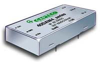
The 40DAW4_1.5 series are specially designed for applications where a wide range input voltage power supplies are isolated from the input power supply in a distributed power supply system on a circuit board. Features:
Application Field:
Download PCB Footprints and Schematic Symbols for free, to download/request, please click the Logo on the right in the below Selection Guide.
| |||||||||||||||||||||||||||||||||||||||||||||||||||||||||||||||||||||||||||||||||||||||||||||||||||||||||||||||||||||
| 40DDW_1.5 | 2“x2“ | 2:1 | 9-18; 18-36; 36-75 | 3.3; 5; 12; 15; ±12; ±15 | 1.5 | • | • | 91% | -40°C - +85°C | 40DDW_1.5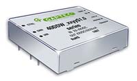
The 40DDW_1.5 series offers 40W of output. wide input voltage of 9-18VDC. 18-36VDC. 36-75VDC Features:
All models are particularly suited to
Download PCB Footprints and Schematic Symbols for free, to download/request, please click the Logo on the right in the below Selection Guide.
| |||||||||||||||||||||||||||||||||||||||||||||||||||||||||||||||||||||||||||||||||||||||||||||||||||||||||||||||||||||
| 40DDW4_1.5 | 2“x2“ | 4:1 | 9-36; 18-75 | 3.3; 5; 12; 15; ±12; ±15 | 1.5 | • | • | 90% | -40°C - +85°C | 40DDW4_1.5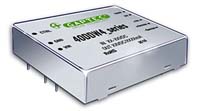
The 40DDW4_1.5 series offers 40W of output. wide input voltage of 9-36VDC & 18-75VDC Features:
All models are particularly suited to
Download PCB Footprints and Schematic Symbols for free, to download/request, please click the Logo on the right in the below Selection Guide.
|
Series |
Case Size |
Input Range |
Input Voltage (VDC) |
Output Voltage (VDC) |
Output Current (A) |
Isolation (kVDC) |
Regulation |
SCP * |
η max. |
Operating Temp. |
Dimming |
Certs |
||||||||||||||||||||||||||||||||||||||||||||||||||||||||||||||||||||||||||||||||||||||||||||||||||||||||||||||||||||||||||||||||||||||
| 50DAW_1.5 | 2“x1“ | 2:1 | 18-36; 36-75 | 3.3; 5; 12; 15; 24 | 1.5 | • | • | 93% | -40°C - +85°C | 50DAW_1.5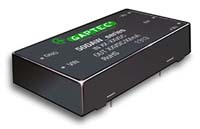
The 50DAW_1.5 series offer 50W of output. with 2:1 ultra wide input voltage of 18-36VDC & 36-75VDC Features:
All models are particularly suited to industrial. tele-communications. test equipments power.
Download PCB Footprints and Schematic Symbols for free, to download/request, please click the Logo on the right in the below Selection Guide.
| |||||||||||||||||||||||||||||||||||||||||||||||||||||||||||||||||||||||||||||||||||||||||||||||||||||||||||||||||||||||||||||||||||||||
| 50QBR_3 | Q-Brick | wide | 66-160 | 24 | 3 | • | • | 92% | -40°C - +100°C | 50QBR_3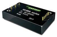
The 50QBR_3 Series is a high performance product designed for the field of railway applications. Output power contains 50W and no min. load requirement. Wide input voltage 66-160VDC, which allows the base plate temperature up to 100°C. Further product features include:
Meets the EN50155 railway standard and UL/EN60950 safety standards. Widely used in the railway system and associated equipment.
Download PCB Footprints and Schematic Symbols for free, to download/request, please click the Logo on the right in the below Selection Guide.
| |||||||||||||||||||||||||||||||||||||||||||||||||||||||||||||||||||||||||||||||||||||||||||||||||||||||||||||||||||||||||||||||||||||||
| 50QBTW12_2.25 | Q-Brick | 12:1 | 9-36; 9-75; 14-154 | 5; 12; 15; 24; ±12; ±15; ±24 | 3 | • | • | 90% | -40°C - +115°C | 50QBTW12_2.25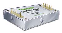
The 50QBTW12_2.25 Series is a high performance product. Output power contains 50W and no min. load requirement. Further product features include:
These dc-dc converter modules use advanced power processing, control and packaging technologies to enhance the performance, flexibility, reliability and cost effectiveness of mature power components.
Download PCB Footprints and Schematic Symbols for free, to download/request, please click the Logo on the right in the below Selection Guide.
|
Series |
Case Size |
Input Range |
Input Voltage (VDC) |
Output Voltage (VDC) |
Output Current (A) |
Isolation (kVDC) |
Regulation |
SCP * |
η max. |
Operating Temp. |
Dimming |
Certs |
||||||||||||||||||||||||||||||||||||||||||||||||||||||||||||||||||||||||||||||||||||||||||||||||||||||||||||||||||||
| 60DAW_1.6 | 2“x1“ | 2:1 | 18-36; 36-72 | 3,3; 5; 12; 15 | 1.6 | • | • | 91% | -40°C - +85°C | 60DAW_1.6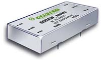
The 60DAW_1.6 series offer 60W of output. with 2:1 ultra wide input voltage of 18-36VDC. 36-72VDC Features:
Field Applications:
Download PCB Footprints and Schematic Symbols for free, to download/request, please click the Logo on the right in the below Selection Guide.
| |||||||||||||||||||||||||||||||||||||||||||||||||||||||||||||||||||||||||||||||||||||||||||||||||||||||||||||||||||||
| 60DAW4_1.6 | 2“x1“ | 4:1 | 9-36; 18-75 | 5; 12; 15; ±5; ±12; ±15 | 1.6 | • | • | 92,5% | -40°C - +85°C | UL60950 | 60DAW4_1.6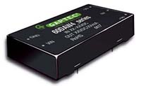
The 60DAW4_1.6 series offer 60W of output. with 4:1 ultra wide input voltage of 9-36VDC. 18-75VDC Features:
Field Applications:
Download PCB Footprints and Schematic Symbols for free, to download/request, please click the Logo on the right in the below Selection Guide.
| ||||||||||||||||||||||||||||||||||||||||||||||||||||||||||||||||||||||||||||||||||||||||||||||||||||||||||||||||||||
| 60DDW_1.5 | 2“x2“ | 2:1 | 18-36; 36-75 | 3.3; 5; 12; 15 | 1.5 | • | • | 90% | -40°C - +70°C | 60DDW_1.5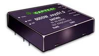
The 60DDW_1.5 series offers 60W of output power. Features
All models are particularly suited to
Download PCB Footprints and Schematic Symbols for free, to download/request, please click the Logo on the right in the below Selection Guide.
| |||||||||||||||||||||||||||||||||||||||||||||||||||||||||||||||||||||||||||||||||||||||||||||||||||||||||||||||||||||
| 60DDW_3 | 2“x2“ | 2:1 | 9-18; 18-36; 36-75 | 5; 12; 15; ±5; ±12; ±15 | 3 | • | • | 88% | -40°C - +80°C | 60DDW_3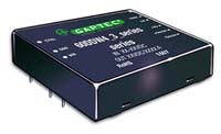
The 60DDW_3 series offers 60W of output and wide input voltage of 18-36VDC. 36-75VDC Features:
All models are particularly suited to
Download PCB Footprints and Schematic Symbols for free, to download/request, please click the Logo on the right in the below Selection Guide.
| |||||||||||||||||||||||||||||||||||||||||||||||||||||||||||||||||||||||||||||||||||||||||||||||||||||||||||||||||||||
| 60DDW4_3 | 2“x2“ | 4:1 | 9-36; 18-75 | 5; 12; 15; ±5; ±12; ±15 | 3 | • | • | 88% | -40°C - +80°C | 60DDW4_3
The 60DDW_3 series offers 60W of output and wide input voltage of 9-36VDC. 18-75VDC Features:
All models are particularly suited to
Download PCB Footprints and Schematic Symbols for free, to download/request, please click the Logo on the right in the below Selection Guide.
|
Series |
Case Size |
Input Range |
Input Voltage (VDC) |
Output Voltage (VDC) |
Output Current (A) |
Isolation (kVDC) |
Regulation |
SCP * |
η max. |
Operating Temp. |
Dimming |
Certs |
||||||||||||||||||||||||||||||||||||||||||||||||||||||||||||||||||||||||||||||||
| 75QBW4_2.25 | Q-Brick | 4:1 | 18-75 | 5; 12; 15; 24; 48 | 2.25 | • | • | 93% | -40°C - +85°C | 75QBW4_2.25
The 75QBW4_2.25 Series is a high performance product with wide input voltage range. Output power contains 75W and no min. load requirement. Wide input voltage 18-75VDC which allows the base plate temperature up to 85°C. Further product features include:
They are widely applied in battery power supplies, industrial control, electricity, instruments, railway, communication, intelligence robot fields.
Download PCB Footprints and Schematic Symbols for free, to download/request, please click the Logo on the right in the below Selection Guide.
| |||||||||||||||||||||||||||||||||||||||||||||||||||||||||||||||||||||||||||||||||
| 75HBW4_1.5 | H-Brick | 4:1 | 9-36; 18-75 | 3,3; 5; 12; 15; 24; 48 | 1.5 | • | • | 85% | -40°C - +100°C | 75HBW4_1.5
The 75HBW4_1.5 Series is a high performance product with wide input voltage range Wide input voltage 9-36VDC or 18-75VDC which allows the base plate temperature up to 100°C. Further product features include:
Download PCB Footprints and Schematic Symbols for free, to download/request, please click the Logo on the right in the below Selection Guide.
| |||||||||||||||||||||||||||||||||||||||||||||||||||||||||||||||||||||||||||||||||
| 75QBR_3 | Q-Brick | wide | 66-160 | 24 | 3 | • | • | 92% | -40°C - +100°C | 75QBR_3
The 75QBR_3 Series is a high performance product designed for the field of railway applications. Output power contains 75W and no min. load requirement. Wide input voltage 66-160VDC which allows the base plate temperature up to 100°C. Further product features include:
Meets the EN50155 railway standard and UL/EN60950 safety standards. Widely used in the railway system and associated equipment.
Download PCB Footprints and Schematic Symbols for free, to download/request, please click the Logo on the right in the below Selection Guide.
|
Series |
Case Size |
Input Range |
Input Voltage (VDC) |
Output Voltage (VDC) |
Output Current (A) |
Isolation (kVDC) |
Regulation |
SCP * |
η max. |
Operating Temp. |
Dimming |
Certs |
||||||||||||||||||||||||||||||||||||||||||||||||||||||||||||||||||||||||||||||||
| 100HBAW_1.5 | H-Brick | 2:1 ; 4:1 | 9-18; 18-36; 9-36; 18-72 | 3.3; 5; 12; 15; 24; 48 | 1.5 | • | • | 90% | -40°C - +85°C | 100HBAW_1.5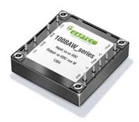
The 100HBAW_1.5 series offers 100W of output. wide input voltage of 2:1 (9-18VDC; 18-36VDC; 36-72VDC) & 4:1 (9-36VDC; 18-72VDC). and features:
All models are particularly suited to tele-communications. industrial. test equipments power etc.
Download PCB Footprints and Schematic Symbols for free, to download/request, please click the Logo on the right in the below Selection Guide.
| |||||||||||||||||||||||||||||||||||||||||||||||||||||||||||||||||||||||||||||||||
| 100QBW4_2.25 | Q-Brick | 4:1 | 18-75 | 5; 12; 15; 24; 48 | 2.25 | • | • | 94% | -40°C - +85°C | 100QBW4_2.25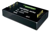
The 100QBW4_2.25 Series is a high performance product with Five-sided metal shielding package.Output power contains 100W and no min. load requirement. Wide input voltage 18-75VDC, which allows the base plate temperature up to 85°C. Further product features include:
Download PCB Footprints and Schematic Symbols for free, to download/request, please click the Logo on the right in the below Selection Guide.
| |||||||||||||||||||||||||||||||||||||||||||||||||||||||||||||||||||||||||||||||||
| 100QBR_3 | Q-Brick | wide | 66-160 | 24 | 3 | • | • | 92% | -40°C - +100°C | 100QBR_3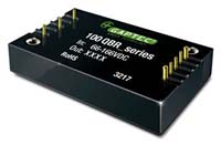
The 100QBR_3 Series is a high performance product designed for the field of railway applications. Output power contains 100W and no min. load requirement. Wide input voltage 66-160VDC, which allows the base plate temperature up to 100°C. Further product features include:
Meets the EN50155 railway standard and UL/EN60950 safety standards. Widely used in the railway system and associated equipment.
Download PCB Footprints and Schematic Symbols for free, to download/request, please click the Logo on the right in the below Selection Guide.
|
Series |
Case Size |
Input Range |
Input Voltage (VDC) |
Output Voltage (VDC) |
Output Current (A) |
Isolation (kVDC) |
Regulation |
SCP * |
η max. |
Operating Temp. |
Dimming |
Certs |
||||||||||||||||||||||||||||||||||||||||||||||||||||||||||||||||||||||||||||||||||||||||||||||||||||||||||||||||||||||||||||||||||||||||||||||||||||||||||||||||||||||||||||||||||||||||||||||||||||||||||||||||||||||||||||||||||||||||||||||||||||||||||||||||||||
| 150HB4_1.5 | H-Brick | 4:1 | 18-72 | 28; 48 | 1.5 | • | • | 80% | -25°C - +85°C | 150HB4_1.5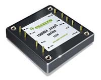
The 150HB4_1.5 series offers 150W of output. wide input voltage of 4:1 (18-72VDC). and features_
All models are particularly suited to tele-communications. industrial. test equipments power etc.
Download PCB Footprints and Schematic Symbols for free, to download/request, please click the Logo on the right in the below Selection Guide.
| |||||||||||||||||||||||||||||||||||||||||||||||||||||||||||||||||||||||||||||||||||||||||||||||||||||||||||||||||||||||||||||||||||||||||||||||||||||||||||||||||||||||||||||||||||||||||||||||||||||||||||||||||||||||||||||||||||||||||||||||||||||||||||||||||||||
| 150QBW4_2.25 | Q-Brick | 4:1 | 18-75 | 12; 24; 48 | 2.25 | • | • | 94% | -40°C - +85°C | 150QBW4_2.25
The 150QBW4_2.25 Series is a high performance product with Five-sided metal shielding package.Output power contains 150W and no min. load requirement. Wide input voltage 18-75VDC, which allows the base plate temperature up to 85°C. Further product features include:
Download PCB Footprints and Schematic Symbols for free, to download/request, please click the Logo on the right in the below Selection Guide.
| |||||||||||||||||||||||||||||||||||||||||||||||||||||||||||||||||||||||||||||||||||||||||||||||||||||||||||||||||||||||||||||||||||||||||||||||||||||||||||||||||||||||||||||||||||||||||||||||||||||||||||||||||||||||||||||||||||||||||||||||||||||||||||||||||||||
| 150HBRW4_3 | H-Brick | 4:1 | 50-160 | 12; 15; 24 | 3 | • | • | 91% | -40°C - +100°C | 150HBRW4_3
The 150HBRW4_3 Series is a high performance railway product with Five-sided metal shielding package.Output power contains 150W and no min. load requirement. Wide input voltage 50-160VDC, which allows the base plate temperature up to 100°C. Further product features include:
Download PCB Footprints and Schematic Symbols for free, to download/request, please click the Logo on the right in the below Selection Guide.
|
Series |
Case Size |
Input Range |
Input Voltage (VDC) |
Output Voltage (VDC) |
Output Current (A) |
Isolation (kVDC) |
Regulation |
SCP * |
η max. |
Operating Temp. |
Dimming |
Certs |
||||||||||||||||||||||||||
| 200QBW4_2.25 | Q-Brick | 4:1 | 18-75 | 12; 24; 48 | 2.25 | • | • | 91% | -40°C - +85°C | 200QBW4_2.25
The 200QBW4_2.25 Series is a high performance product with Five-sided metal shielding package.Output power contains 200W and no min. load requirement. Wide input voltage 18-75VDC, which allows the base plate temperature up to 85°C. Further product features include:
Download PCB Footprints and Schematic Symbols for free, to download/request, please click the Logo on the right in the below Selection Guide.
|
Series |
Case Size |
Input Range |
Input Voltage (VDC) |
Output Voltage (VDC) |
Output Current (A) |
Isolation (kVDC) |
Regulation |
SCP * |
η max. |
Operating Temp. |
Dimming |
Certs |
||||||||||||||
| 450HBAW_1.5 | H-Brick | 2:1 | 36-75 | 28; 48 | 1.5 | • | • | 94,5% | -40°C - +100°C | UL60950 | 450HBAW_1.5
The 450HBAW_1.5 Series are half-brick DC/DC converters that provide a high efficiency single output. The remote control option is negative logic. The output voltage trim option is positive. Wide input voltage 36-75VDC, which allows the base plate temperature up to 100°C. Further product features include:
Applications
Download PCB Footprints and Schematic Symbols for free, to download/request, please click the Logo on the right in the below Selection Guide.
|
Series |
Case Size |
Input Range |
Input Voltage (VDC) |
Output Voltage (VDC) |
Output Current (A) |
Isolation (kVDC) |
Regulation |
SCP * |
η max. |
Operating Temp. |
Dimming |
Certs |
||||||||||||||
| 500HBAW_1.5 | H-Brick | 2:1 | 36-75 | 50 | 1.5 | • | • | 93% | -40°C - +100°C | UL60950 | 500HBAW_1.5
The 500HBAW_1.5 Series are half-brick DC/DC converters that provide a high efficiency single output. The remote control option is negative logic. The output voltage trim option is positive. Wide input voltage 36-75VDC, which allows the base plate temperature up to 100°C. Further product features include:
Applications
Download PCB Footprints and Schematic Symbols for free, to download/request, please click the Logo on the right in the below Selection Guide.
|
Series |
Case Size |
Input Range |
Input Voltage (VDC) |
Output Voltage (VDC) |
Output Current (A) |
Isolation (kVDC) |
Regulation |
SCP * |
η max. |
Operating Temp. |
Dimming |
Certs |
||||||||||||||
| 700HBAW_1.5 | H-Brick | 2:1 | 36-75 | 28; 50 | 1.5 | • | • | 94% | -40°C - +100°C | UL60950 | 700HBAW_1.5
The 700HBAW_1.5 Series are half-brick DC/DC converters that provide a high efficiency single output. The remote control option is negative logic. The output voltage trim option is positive. Wide input voltage 36-75VDC, which allows the base plate temperature up to 100°C. Further product features include:
Applications
Download PCB Footprints and Schematic Symbols for free, to download/request, please click the Logo on the right in the below Selection Guide.
|

